Firmware user manual for the Ornament & Crime eurorack module.
This documentation is for v1.2 firmware. Documentation for earlier versions can be found here.
Overview

-
the Ornament & Crime firmware is a collaborative open-source project by Patrick Dowling (aka pld), Max Stadler (aka mxmxmx) and Tim Churches (aka bennelong.bicyclist). It (considerably) extends the original firmware for the Ornament & Crime (o_C) DIY eurorack module, designed by mxmxmx.
-
the original o_C module was designed to perform a single function: a digital, quantising version of the classic analogue shift register (ASR).
-
there is still a quantising ASR (analogue shift register) function in the current Ornament & Crime firmware, now named CopierMaschine, but several other “apps” have been added, incl. quantisers, sequencers, LFOs, random/chaotic CV generators, and so on. These apps are selectable on-the-fly, without having to reboot the module or toggle the power.
-
the o_C module, and the firmware for it, break new ground as a polymorphic module: a generic set of inputs and outputs are provided, and the textual OLED display is used to permit re-mapping of these inputs and outputs for each app, and in some cases, for each of the four channels within each app. The o_C module does not purport to be the paradigmatic pinnacle of polypurpose — in fact, as noted above, it was originally designed to fulfil just one purpose (ASR) — but together with the much-expanded firmware for it, we hope it provides an interesting and useful early step in the evolution of such multi-purpose modules.
The apps currently available in Ornaments & Crimes are:
- CopierMaschine is an enhanced version of the original quantising digital emulation of a four stage analogue shift register (ASR).
- Harrington 1200 provides basic neo-Riemannian Tonnetz transformations of triadic chords, triggered by the digital (gate/trigger) inputs.
- Automatonnetz combines Tonnetz transforms with a “vector” sequencer - it can be both a chord sequencer and a melody sequencer, but not of the usual kind.
- Quantermain is a quad pitch quantiser for external voltages, with editable scales; it can do clocked (trigger-driven) quantising, or continuous quantising, with a latency of under 100 microseconds; it also features quad Turing Machines, May-Verhulst logistic maps or byte beats as optional, semi-random, internally generated CV sources.
- Meta-Q is a dual-channel quantiser, similar to Quantermain, but also offering scale and note mask sequencing.
- Quadraturia is a wavetable quadrature LFO, based on the “Easter egg” in the Mutable Instruments Frames module.
- Low-rents is a dual Lorenz and Rössler (strange attractor) modulation generator, partially based on the “Easter egg” in the Mutable Instruments Streams module.
- Piqued is a quad voltage-controlled envelope generator, based on envelope generator code from the Mutable Instruments Peaks module, but extending it with voltage control, additional envelope types, including re-triggering (looping) envelopes, additional segment shapes, adjustable trigger delays, and a unique Euclidean “trigger filter” which turns the app into a Euclidean rhythm generator which can output envelopes, not just gate or trigger pulses.
- Sequins is a dual-channel step sequencer offering 4 “tracks” of up to 16 steps each; tracks can themselves be sequenced.
- Dialectic Ping Pong is a quad bouncing ball envelope generator, based on a hidden mode of the Mutable Instruments Peaks module.
- Viznutcracker, sweet! is a quad “byte beat” equation generator, which can be used as an audio source to generate curious but often interesting 8-bit noises and tunes, or which can be clocked by an external source to produce “byte beat” control voltage sequences. “Byte beats” were first described in 2011 by viznut (aka Ville-Matias Heikkilä).
- References is a simple utility app that outputs specific reference voltages on each channel to help tune or calibrate VCOs and other modules.
For information about the o_C module hardware, including DIY build details, please start here.
Operational principles
Startup
Immediately after power-on, the start-up phase is indicated by a line at the bottom of the display which progressively shrinks right-to-left. By default, following start-up phase, the module boots into the last saved app, unless one of the encoders is held down:
- hold down the Left encoder: Boot into calibration mode (unchanged from the original o_C firmware - please see the calibration procedure here
- hold down the Right encoder: Enter the app selection menu
App Selection
The app selection menu can be reached either when the module is first powered on, as described above, or by depressing the right encoder for two seconds or longer (a long press) during normal use.
- Turn the right encoder to select an app.
- Press the right encoder to switch to the selected app.
- Pressing the Up button (the upper button to the right of the display) while the App Selection screen is displayed toggles encoder acceleration on and off (there is no visual indication of this). Encoder acceleration increases the amount by which values are incremented or decremented on each encoder rotational click when you are rapidly spinning the encoder in value edit mode, rather than advancing it slowly one click at a time. This speeds up sweeping across the full range of values, while still retaining full precision when moving the encoder one step at a time.
Save Settings / Module State
The settings for each o_C app are NOT saved automagically. To save the current state/settings, enter the app selection menu (see above), then long press the right encoder (> 2s) a second time to save the module state and make the selected app the default at the next boot. A confirmatory message (saving..... ) will briefly be displayed. Note that the current settings for all apps are saved each time you save the settings, not just the settings for the currently selected app.
- Note: the operation of the module is briefly paused while the settings are saved. (That’s intentional). Normally this pause is of no consequence, but you may need to take it into account if/when you are using your o_C in a live performance setting. The module does not pause when switching from one app to another, only when settings are saved.
- The settings are saved permanently in the Teensy 3.2 EEPROM storage. (EEPROM memory can only be written to a certain number of times before it becomes unreliable. The EEPROM storage is good for at least 100,000 write cycles, and probably a lot more. Meaning, you are very unlikely to wear out the EEPROM memory in the Teensy/MK20 processor in normal use.)
General operation of the apps
Each app has two display pages, a settings mode and a “screensaver” mode. The apps drop into screensaver mode after a short period of inactivity (that is, no user interaction); the timeout period can be set in the calibration menu. Alternatively, long press (> ~ 1.5 sec) the up button to preview the screensaver.
-
In the background, the module functions the same regardless of whether settings are displayed or the screensaver is displayed. When the screensaver is displayed, clicking or rotating either of the two encoders, or pressing the Up or Down buttons will immediately swap to the settings display.
-
In settings mode, for most of the apps, the right encoder is used to scroll up and down the list of available settings, and clicking on the right encoder will toggle edit mode, indicated by one or two small up/down triangles next to the setting. Turning the right encoder when in edit mode will increment (increase) or decrement (decrease) the relevant setting. Clicking again on the right encoder toggles back to settings selection mode.
-
In multi-channel apps, the left encoder selects which of the four channel (A to D) settings are currently displayed (and editable). All channels remain active in the background, all the time, even while editing settings. The channel can be changed even when value edit mode is active, making it easy to edit the same setting on each ofthe four channels.
-
In other apps, the left encoder is used to set a root note or a transposition, or to set frequency or rate. Its exact behaviour is noted below in the documentation for each of the apps.
-
The two buttons to the right of the display (the Up and Down buttons) either transpose notes up or down an octave, or increase or decrease frequency or speed in steps of 32 (with a few exceptions for some apps, as noted below).
The Apps
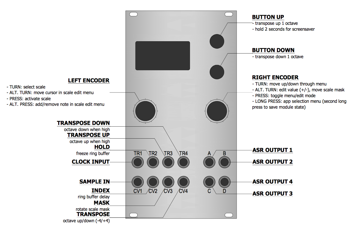
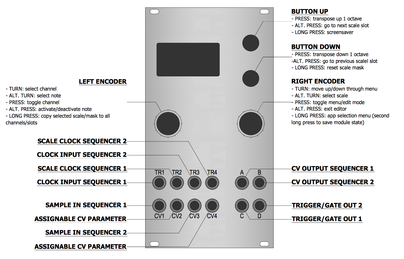
CopierMaschine
Works much the same as the original o_C / quantising ASR firmware. Except, the mode now incorporates some of the new/improved quantiser features, including a larger selection of (editable) preset scales as well as advanced user-scale-edit options (for details, see the Quantermain “app” below).
In essence, then, ASR mode works as a cascaded, four-stage sample-and-hold module (see here for a classic exposition):
- Feed a pulse into the left-most digital input (TR1), and some CV signal (LFO, ADSR, etc) into the leftmost CV input (CV1): on receiving a/the clock, the DAC outputs will be updated, ASR-style: the sampled value will be present at output A, the previous sample values shifted down the remaining outputs B, C, and D:
-
The ASR mode features additional parameters, including
- a rudimentary delay (= controlled via the
indexparameter (CV2)) - scale ‘mask’ rotation (CV3)
- hold (= “freeze” the sample buffer) (TR2)
- transposition (in octaves) (TR3, TR4, CV4)
- a rudimentary delay (= controlled via the
-
The
indexparameter works as a delay, sort of: internally, the ASR is a ring-buffer and (to simplify things) outputs the sampled values S[x] stored at the buffer locations index * output-stage, ie A = S[i * 1], B = S[i * 2], C = S[i * 3], and D = S[i * 4]. -
The default index setting is 0 (internally i = 1), in which case things boil down to standard ASR behaviour:
A = S[1], B = S[2], C = S[3], and D = S[4]
-
If the index parameter was set to, say, i = 8, the ASR will now output the values stored in the buffer at locations S[8], S[16], S[24], and S[32], thus delaying output A by 8 clocks, B by 16 clocks, and so on. Ie, modulating the
indexparameter doesn’t just delay but allows to create different patterns (based on the contents of the buffer). The size of the buffer is 256. -
When the
holdinput goes high (using a gate or the like), no further samples will be acquired; when clocked, the four outputs then simply cycle through what’s already the buffer. -
Please see the discussion of the
Trigger delaymenu selection in the Quantermain app documentation below — the same considerations apply to the eponymous setting in CopierMaschine.
Inputs and outputs
| I/O | Function |
|---|---|
| TR1 | Clock input |
| TR2 | Hold (freeze ring buffer) |
| TR3 | Transpose: Octave up, when high |
| TR4 | Transpose: Octave down, when high (overridden by TR3) |
| CV1 | Sample in |
| CV2 | Index: ring buffer index (= “delay”) |
| CV3 | Mask: rotate scale mask |
| CV4 | Transpose: octave up/down (-4/+4) |
| A, B, C, D | ASR outputs 1-4 |
Controls
| Control | Function |
|---|---|
| Left encoder (turn) | Select scale in main menu; move cursor in scale edit menu |
| Left encoder (press) | Activate scale in main menu; add/remove note in scale edit menu |
| Right encoder (turn) | Navigation mode: move up and down through the menu items. Edit mode: increase or decrease the value being edited; move scale “mask” in scale edit menu |
| Right encoder (press) | Toggle between menu navigation (selection) mode and value editing mode |
| Right encoder (long press) | App selection menu |
| Up button | Transpose up: one octave |
| Down button | Transpose down: one octave |
Available settings (per-channel)
| Setting | Meaning |
|---|---|
scale |
Current scale |
Root |
Root note for scale |
Active notes |
“scale mask” / active note pattern in the selected scale |
Index |
ring buffer index (= “delay”) amount |
Mult/att |
CV “gain”, multiplies incoming CV sample value by selected value (range: 0.1 - 2.0) |
Trigger delay |
sets the delay between receiving a trigger (for details see Quantermain below below) |
CV source |
sets the source of the CV, either an external voltage, or an internal source (for details see below) |
Scale edit:
see here (user-scales are shared across apps).
Screensaver display
Four little “Arabesque” patterns, representing the pitch CV output on each of the four channels.
CV sources
Four settings of the CV source parameter are available:
CV1— voltages on the CV1 input are quantised, according to thescaleandActive notessettings.TM— “Turing Machine” (also referred to as a linear-feedback shift register or LFSR, elsewhere in this documentation). This is the same as theTuringsource in the Quantermain app - please see the discussion of the Turing Machine source in the Quantermain section for further details of operation. The available settings for the Turing Machine source in CopierMaschine are shown in the table below.ByteB— “bytebeat” equations used to generate semi-fractal note values, rather than audio signals (which is what byte beat equations are usually used for). Please see the Viznutcracker, sweet! app for details of the byte beat equations available.IntSq— integer sequences - several classes of random and fractal integer sequences, used as note values.
Turing Machine source settings in CopierMaschine
Note: LFSR is used equivalently to “Turing Machine” here. (see Quantermain for details).
| Setting | Meaning |
|---|---|
LFSR length |
Length of the linear feedback shift register, in bits, range 4 to 32 |
LFSR p |
Probability that the least significant bit will be flipped when it to copied, range 0 to 255 (0 means p= 0, 255 means p= 1) |
LFSR range |
output range, 1 (min) - 120 (max) |
LFSR CV1 |
The Turing Machine parameter to which any voltage input on CV1 will be directed. Choices are rng, len and p (ie, range, length, and probability) |
Byte beats source settings in CopierMaschine
| Setting | Meaning |
|---|---|
BB eqn |
sets the byte beat equation used as the source. See the Viznutcracker, sweet! app documentation for more details of the currently available equations. |
BB P0 |
Parameter 0 for the byte beat equation - see See the Viznutcracker, sweet! app documentation for more details. |
BB P1 |
Parameter 1 for the byte beat equation - see See the Viznutcracker, sweet! app documentation for more details. |
BB P2 |
Parameter 2 for the byte beat equation - see See the Viznutcracker, sweet! app documentation for more details. |
BB CV1 |
The byte beat parameter to which the input on CV1 is directed. Possible destinations are “M/A”, “EQN”, “P0”, “P1”, “P2”. See LFSR CV1 above for details of input voltage ranges. |
Note that compared to the bytebeat source in Quantermain, a Bytebeat range parameter is missing from CopierMaschine. The reason is that the M/A setting has the same effect in CopierMaschine when the ByteB source is used as the Bytebeat range setting does in Quantermain.
Integer sequence source settings in CopierMaschine
| Setting | Meaning |
|---|---|
IntSeq |
sets the integer sequence used as the source. See below for a list of available integer sequences and their characteristics. |
IntSeq modul |
sets the modulus for the integer sequence. The value of the integer from the integer sequence is divided by the modulus and the remainder is used. For example, if the modulus is 8 and the current integer value from the sequence is 19, then the remainder of 19 - (2 x 8) i.e. 3 is used as the value. In other words, values “wrap around” at the modulus setting — it sets a maximum note range for the integer sequence, similarly to the M/A setting, but M/A compresses of expands the range of notes for a given integer value from the sequence, whereas the modulus wraps the values around. |
IntSeq start |
sets the start point in the stored integer sequence. The stored sequences are 256 steps long, and the maximum start point is 254 to ensure a minimum sequence length of 2. |
IntSeq len |
sets the length of the integer sequence. Thus a length of 16 will use just 16 values from the stored 256 step sequence, starting at the step specified by IntSeq start. |
IntSeq dir |
sets whether the integer sequence loops back to the beginning when it gets to the end, or whether it swings back like a pendulum and plays in reverse when it reaches the end. The “end” is the last step in the sequence, as defined by the sequence start plus the sequence length settings. |
Fractal stride |
Two of the sequences are fractal in nature, and the “stride” setting sets how many steps are advanced on each trigger input. This also works with the non-fractal sequences and provides additional variation, particularly if the stride is not an exact divisor of the sequence length. |
IntSeq CV1 |
The integer sequence parameter to which the input on CV1 is directed. Possible destinations are (parameter names in brackets): M/A (mult/att), seq (IntSeq), strt (IntSeq start), len (IntSeq len), strd (Fractal stride) and mod (IntSeq modul). See LFSR CV1 above for details of input voltage ranges. |
Integer sequences available in CopierMaschine and Quantermain
| Menu name | Description |
|---|---|
pi |
The first 256 digits of π |
phi |
The first 256 digits of φ |
tau |
The first 256 digits of τ |
Euler |
The first 256 digits of Euler’s number, e. |
root2 |
The first 256 digits of the square root of 2. |
vnEck |
The first 256 integers in van Eck’s sequence. |
ssdn |
The first 256 integers in the sequence of the sum of squares of the digits of n. |
Dress |
Dress’s sequence. |
PNinf |
Per Nørgård’s infinity series |
See the acknowledgements section for additional references for some of these integer sequences.
Note that there isn’t really anything magical or mystical about the digits of transcendental numbers such as π — they are just a convenient source of sequences of digits. However, if you use them to make music, then you can post videos like this, or this.
Harrington 1200
This is a relatively straight-forward implementation of neo-Riemannian transformations for generating triad (three note chord) progressions (see the acknowledgements section for more details on neo-Riemannian music theory).
- In settings mode, the top line of the display shows, from left to right:
- the current root note for the root (initial) chord
- the musicological mode (major or minor) for the root chord
- the three notes comprising the current triad being output. Clicking on the left encoder toggles between note display and display of semitone offset from the root note.
-
The root note can be changed using the
Transposesetting in the menu. The left encoder can also be used to change this setting at any time (such as during live performance). The voltage input on CV1 also changes the root note (i.e. the transposition). -
The musicological mode of the root chord is set by
Root modein the menu to either major or minor. Chord inversion is similarly set using theInversionmenu item. The voltage input on CV4 also changes the inversion. -
The pitch voltage (scalled to 1V/octave) for the root note appears on output A. The pitch voltages for the three notes of the current triad appear on outputs B, C and D. Thus, to pproduce chords, you should feed the B, C and D outputs into the 1V/octave pitch inputs of three VCOs.
-
Trigger inputs TR2, TR3 and TR4 are used to apply the atomic P, L or R transformations, or the compound N, S or H transformations (see below), depending on the
Trigger typesetting. Trigger input TR1 resets the current triad back to the root chord for all settings ofTrigger type1. -
If multiple triggers are received, the reset input (TR1) always has priority, then all triggered transforms are applied. The order in which they are applied can be set in the menu by the
PLR PriorityandNHS Prioritysettings. -
The neo-Riemannian transformations themselves are quite simple, and “reversible” i.e. applying them twice returns the original triad. The following basic (atomic) tranformations are provided:
- P (Parallel): Moves the third up or down a semitone, thus P(Cmaj) = Cmin, P(Cmin) = Cmaj.
- L (Leittonwechsel): Converts a major triad to a minor by shifting the root down a semitone and making the third the root, or from minor to major by moving the fifth up a semitone to become the root.
- R (Relativ): Converts a major triad to its relative minor, or a minor triad to its relative major.
-
Alternatively, secondary transformations can be used:
- N (Nebenverwandt): Exchanges a major triad for its minor subdominant, and a minor triad for its major dominant (e.g. C major and F minor). The “N” transformation is the same as applying R, L, and P successively.
- S (Slide): Exchanges two triads that share a third (e.g. C major and C♯ minor); it is the same as applying L, P, and R successively, in that order.
- H (Hexatonic): Exchanges a triad for its hexatonic pole (e.g. C major and A♭ minor); it is the same as applying L, P and L transformations successively.
-
The implementation computes these N, S and H transformations in a single step however, not sequentially.
-
Note that in trigger modes
PLRandNSH, only PLR or NSH transformations can be applied, but not mixtures of both. However, inEucl(Euclidean) trigger mode (see below), mixtures of both PLR atomic transformations and NSH secondary or compound transformations can be applied. - Internally, the triad is stored in a neutral form (basically just offsets), thus the chord voicing is preserved and can be shifted easily to the quantised root note, and inversions created on-the-fly. For an alternate way of implementing these transformations, see the documentation of the Tonnetz Sequent.
Screensaver display
The current triad (output as pitch CVs on the B, C and D sockets) is shown graphically on the left. The circumference of the circle has 12 points on it, one point for each semitone in an octave, with C at the 12 o’clock position. The current triad is indicated by the three dots, joined to form a triangle. The middle section of the screensaver display shows the last four transformations applied, with the most recent one at the top. The rightmost section indicated the current triad being output, with numbers showing the octave for each note.
Tip: for a pretty display, patch the output of an LFO into CV1 in order to rapidly rotate the root note up and down.
Settings
| Setting | Meaning |
|---|---|
Transpose |
Shift root/triad in semitones, range -24 to 24 (i.e. two octaves up or down) |
Transpose CV |
Selects CV input used to shift root/triad in semitones, up (positive voltages up to about 6.5V) or down (negative voltages down to about -3.5V). Transposition should be scaled at 1V/octave. Choices are None, CV1, CV2, CV3, CV4. |
Octave |
Shift root/triad in octaves, range -3 to 3. |
Octave CV |
Selects CV input used to shift root/triad in semitones, up (positive voltages up to about 6.5V) or down (negative voltages down to about -3.5V). Scaling is not 1V/octave. Choices are None, CV1, CV2, CV3, CV4. |
Root mode |
Mode of root triad, either maj or min |
Inversion |
Chord inversion, range is from -3 to 3. |
Inversion CV |
Selects CV input used to shift the chord inversion, up (positive voltages up to about 6.5V) or down (negative voltages down to about -3.5V). Choices are None, CV1, CV2, CV3, CV4. |
PLR Priority |
Order in which the P, L and R transforms are applied if multiple triggers on TR2, TR3 and TR4 are received simultaneously |
PLR Prior CV |
Selects CV input used to shift the PLR priority amongst the available choices, up (positive voltages up to about 6.5V) or down (negative voltages down to about -3.5V). Choices are None, CV1, CV2, CV3, CV4. |
NSH Priority |
Order in which the N, S and H transforms are applied if multiple triggers on TR2, TR3 and TR4 are received simultaneously |
NSH Prior CV |
Selects CV input used to shift the NSH priority amongst the available choices, up (positive voltages up to about 6.5V) or down (negative voltages down to about -3.5V). Choices are None, CV1, CV2, CV3, CV4. |
CV sampling |
Selects how sampling of CV1, CV2, Cv3 and CV4 inputs is done: either continuously (Cont) or on a sample-and-hold basis (Trig) which is triggered by a trigger on any or all of the four trigger inputs. |
Output mode |
Output mode, with the default being chord, or use tune to output the quantised root on all four output channels |
Trigger type |
Sets the trigger behaviour, either P. L and R transforms triggered by trigger inputs on TR2, TR3 and TR4 respectively, or N, S or H transforms, also triggered bt TR2, TR3 or TR4 respectively, or Eucl, which enable Euclidean trigger masks - see below for details. |
Controls
| Control | Function |
|---|---|
| Left encoder (turn) | Root note transpose up or down |
| Left encoder (press) | Toggle display of note numbers (semitone offsets from the root note) or names (note: the names are the simplest possible mapping, thus there are no enharmonic substitutions) |
| Left encoder (long press) | Reset to defaults |
| Right encoder (turn) | Navigation mode: move up and down through the menu items. Edit mode: increase or decrease the value being edited. |
| Right encoder (press) | Toggle between menu navigation (selection) mode and value editing mode |
| Right encoder (long press) | App selection menu |
| Up button | Increment chord inversion by 1 |
| Down button | Decrement chord inversion by 1 |
Inputs and outputs
| I/O | Function |
|---|---|
| TR1 | Reset to root triad |
| TR2 | P transform (if Trigger type is PLR), or N transform (if Trigger type is NSH), or clock input (if Trigger type is Eucl) |
| TR3 | L transform (if Trigger type is PLR), or S transform (if Trigger type is NSH), or clock input (if Trigger type is Eucl) |
| TR4 | R transform (if Trigger type is PLR), or H transform (if Trigger type is NSH), or clock input (if Trigger type is Eucl) |
| CV1 | Mapped according to Transpose CV, Octave CV, Inversion CV, PLR Prior CV and NSH Prior CV settings (see table above), as well as according to the Eucl CV1 map, Eucl CV2 map, Eucl CV3 map and Eucl CV4 map settings (see below) - each CV input can be used for multiple internal destinations. |
| CV2 | Ditto |
| CV3 | Ditto |
| CV4 | Ditto |
| A | Quantised root |
| B, C, D | Transformed & inverted triad (also quantised) |
Euclidean trigger masks
Euclidean trigger mask mode in the Harrington 1200 app is enabled by setting the Trigger type setting to Eucl. Twenty-two additional settings will appear in the menu when the Eucl trigger type is selected. In this mode, a simple, single, regular clock input can be used (into TR2, TR3 or TR4) to trigger P, L, R, N, S or H chord transformations. Each of the six transformation types has its own “Euclidean mask” or “Euclidean filter” — by varying the parameters on each of these for each transformation type, very complex “polyrhythms” of chord transformations can be derived from as single regular clock input. Furthermore, all of the Euclidean trigger mask parameters, for each transformation type, can be placed under external voltage control. This permits external voltages to influence complex, evolving patterns of chord transformations driven by a single external clock.
Each type of transformation (P, L, R, N, S and H) has three settings controlling the Euclidean trigger mask (Euclidean filter) for it (thus 18 controls all together): the length of the Euclidean pattern (named X EuLeng, where X is the type of transformation, one of P, L, R, N, S or H), the fill amount (X EuFill) for that length of pattern, and the offset or rotation (X EuOffs) of the pattern. These all operate in the same way as the Euclidean trigger filters for the envelope generators in the Piqued app operate - see the discussion in the Piqued section for further details.
The settings Eucl CV1 map through to Eucl CV4 map permit the four external voltage inputs to be mapped to four of the 18 available Euclidean trigger mask settings. The same input voltages can also be used to simultaneous control transposition, octave, inversion and trigger priorities (see above), if desired.
Tips
Try using a rhythm generator, such as the Mutable Instruments Grids module, or the ALM/Busy Circuits Pamela’s Workout module, or the Rebel Technology Stoicheia module, or some combination of clock division and logic modules, or even a second o_C module running the Piqued app with Euclidean trigger filters engaged, to trigger the P, L and R transformations (via trigger inputs TR2, TR3 and TR4) in varying patterns to create a variety of chord progressions that may or may not be musically pleasing, or interesting, or horrifying.
Update: in v1.2, you can use the built-in Euclidean trigger masks to achieve the same thing, and more, with just a single external regular clock input (into TR2, TR3 or TR4).
Automatonnetz
This app uses the neo-Riemannian transformations implemented in the Harrington 1200 app (see above), but with the sequence of transformations determined not through triggers for each type of transformation, but rather by navigating a 5x5 grid of cells. On each clock input the dx (delta x) and dy (delta y) — hence “vector” sequencer — values are added to the current position on the grid to determine the next cell. The position simply wraps around when it reaches the edge of the grid, and “backwards” motion is also possible. The position and movement can also be fractional, allowing for clock divisions and all kinds of patterns.
Each cell of the grid can contain a neo-Riemannian transformation, or a reset, as well as other parameters. In this app, there are three additional transforms available, which can be represented as a combination of the basic three neo-Riemannian transforms:
- S (Slide): LPR, example S(Cmaj) = C#min
- H (Hexatonic): LPL, example H(Cmaj) = A-min
- N (Nebenverwandt): RLP, example N(CMaj) = Fmin
The implementation computes these in a single transform step however, not sequentially.
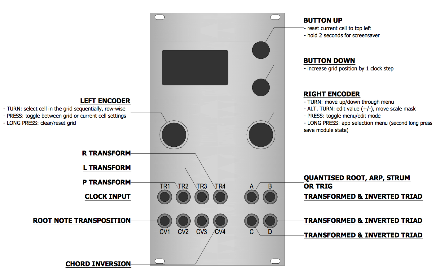
Controls
| Control | Function |
|---|---|
| Left encoder (turn) | Select cell in the grid — the 25 cells are accessed sequentially, row-wise. |
| Left encoder (press) | Toggle between editing overall grid settings or current cell settings |
| Left encoder (long) | Clear/reset grid (the results of this action depends on Clr setting) |
| Right encoder (turn) | Navigation mode: move up and down through the menu items. Edit mode: increase or decrease the value being edited. |
| Right encoder (press) | Toggle between menu navigation (selection) mode and value editing mode |
| Right encoder (long press) | App selection menu |
| Up button | Reset current cell position to grid origin (top left-hand corner of grid) |
| Down button | Increment grid position by one clock step |
Grid settings
| Setting | Meaning |
|---|---|
dx |
Amount of movement along x-axis (horizontal) per clock input |
dy |
Amount of movement along y-axis (vertical) per clock input |
Mode |
Musicological mode of root triad, either maj or min |
Oct |
Move outputs up/down in octave steps |
OutA |
Switch output mode of channel A: root outputs root note, trig outputs a trigger whenever the triad output on B, C and D is transformed, arp arpeggiates the current triad, strm (strum) arpeggiates the triad once only as soon as the triad transformation has taken place (tip: very useful with the Mutable Instruments Elements or Rings modules, or Mutable Instruments Braids in “PLUK” mode) |
Clr |
Sets how the grid is cleared on a long-press of the left encoder. zero clears the grid, rT fills with random transforms, rTev sets each cell’s event to randT |
Per-cell settings
| Setting | Meaning |
|---|---|
Trfm |
Determines the transform which is applied when this cell is active; special values are @ (reset) and * (no transform) |
Offs |
Offset in semitones applied while this cell is active |
Inv |
Inversion of the transformed triad |
Muta |
Mutation event that is applied when the cell is left (i.e. on the next clock after the cell’s transform is applied). Valid values are shown in the table below. Note that this setting makes the grid self-modifying as the current cell traverses it! |
Muta setting |
Action |
|---|---|
none |
nothing happens |
rT__ |
The transformation for this cell is set to a random value. |
r_O_ |
The transposition for this cell is set to a random value. |
rTO_ |
The transformation and the transposition for this cell is set to a random value. |
r__I |
The inversion for this cell is set to a random value. |
r_OI |
The transposition and the inversion for this cell is set to a random value. |
rTOI |
The transformation, the transposition and the inversion for this cell is set to a random value. |
Input/output assignment
| I/O | Function |
|---|---|
| TR1 | Clock/trigger input to increment steps in the sequencer |
| TR2 | Arpeggiator clock (if mode is arp or stem) |
| TR3 | |
| TR4 | If high, inhibits arpeggiator clock |
| CV1 | The voltage on this input is quantised to the root note of triad (before transform) - that is, it provides external voltage control of the root note (same as Harrington 1200) |
| CV2 | |
| CV3 | |
| CV4 | Modulate triad inversion (same as Harrington 1200) |
| A | Depending on the OutA setting: pitch CVs for quantised root note, arppegio/strum, or trigger out |
| B, C, D | Pitch CVs for the triad after transformation |
Screensaver display
Similar to Harrington 1200 app, the current triad (output as pitch CVs on the B, C and D sockets) is shown graphically on a pitch circle on the left. On the right, the last few vector moves are shown as a “snake”. The current output triad is also displayed.
Tips
If you wish to use the vector sequencer to play melodies, then set the TRFM (transform) value for every cell in the grid to * (null transform), and set the Offs value for each cell to a specific note offset from the root note that you want to appear in your sequence. Then, as the current cell is moved around the grid by clock/trigger inputs on TR1, the note defined for that cell will be output on output B (with transpositions of the same note sequence on outputs C and D).
Quantermain
4 channel quantizer, integrates the quantiser from the Mutable Instruments Braids module, but expands it with interactive scale-edit functionalities (48 editable preset scales are included, plus 4 fully user-definable scales (with a maximum of 16 notes and additional finetune/microtonal edit options)). for further information re custom scales see here.
-
the output accuracy should be excellent (is fairly excellent) due to the use of the precision TI 16-bit DAC; the trigger-to-quantised-output latency is also very decent: < 100 microseconds.
-
the four channels are fully independent, but can be slaved to the same clock and/or track the same CV sources, if desired. here’s the default mapping:
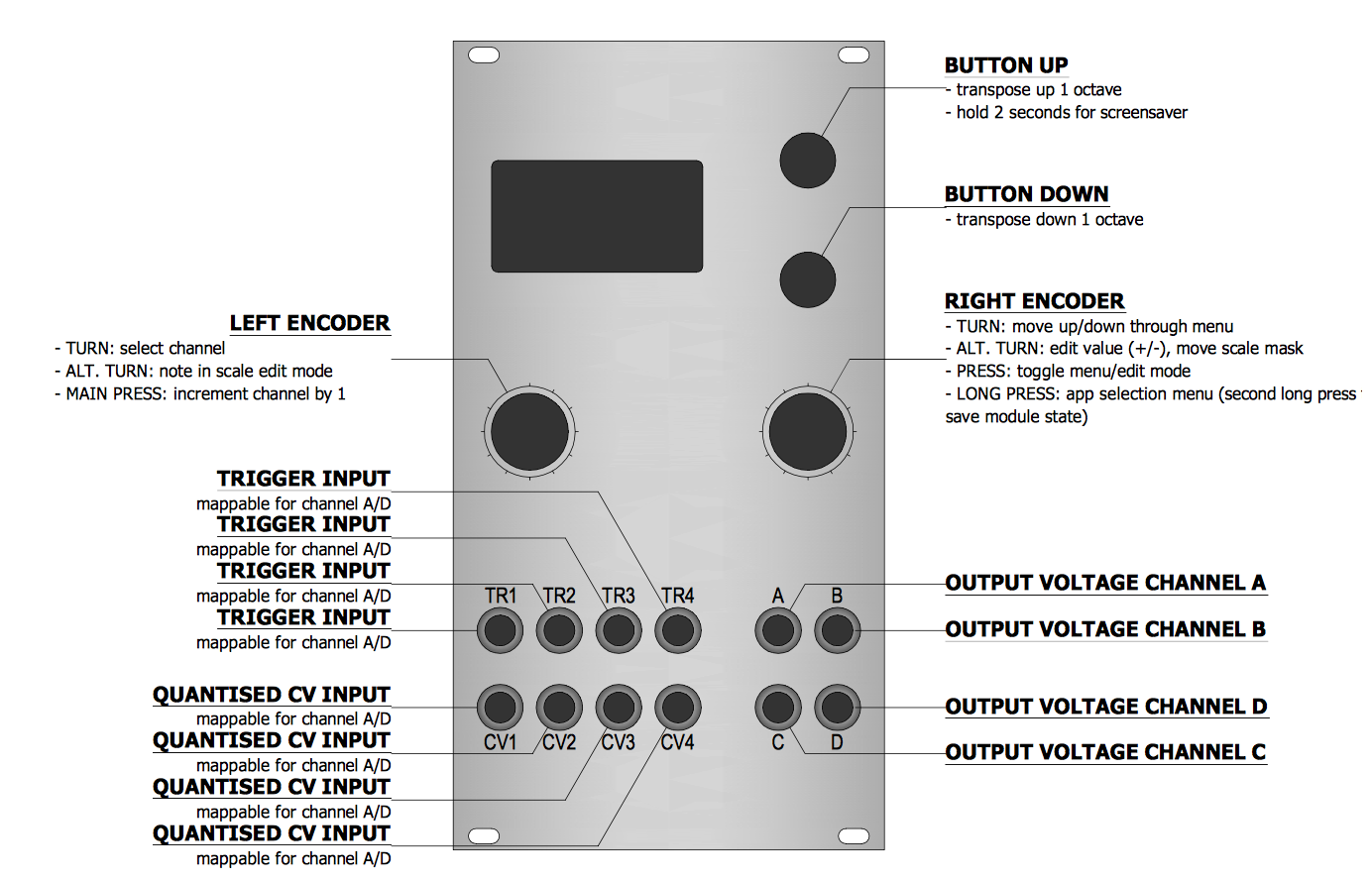
Input/output assignment
| I/O | Function |
|---|---|
| TR1, TR2, TR3 & TR4 | Mappable as the trigger input for each channel A to D, independently (except when Trigger source is set to cnt+ or cnt- — see below) |
| CV1, CV2, CV3 & CV4 | Mappable as the external CV input to be quantised for each channel A to D, independently, or can be mapped to control various parameters when internal CV “sources” (e.g. built-in Turing Machines) are used. |
| A | Output voltage for channel A (quantised if quantisation is enabled) |
| B | Output voltage for channel B (quantised if quantisation is enabled) |
| C | Output voltage for channel C (quantised if quantisation is enabled) |
| D | Output voltage for channel D (quantised if quantisation is enabled) |
Controls
| Control | Function |
|---|---|
| Left encoder (turn) | Select channel, or note in scale in scale edit mode |
| Left encoder (press) | Increment channel by one |
| Right encoder (turn) | Navigation mode: move up and down through the menu items. Edit mode: increase or decrease the value being edited. |
| Right encoder (press) | Toggle between menu navigation (selection) mode and value editing mode |
| Right encoder (long press) | App selection menu |
| Up button | Transpose up one octave for currently displayed channel |
| Down button | Transpose down one octave for current displayed channel |
| Up button long | screen saver short cut |
| Down button down | reset scale mask |
Available settings (per-channel)
| Setting | Meaning |
|---|---|
scale |
Current scale |
Root |
Root note for scale |
Active notes |
“scale mask” / active note pattern in the selected scale |
CV Source |
external CV source (CV1 to CV4) or internal value sources (Turing Machine or Lgstc (logistic map) or ByteB (byte beats) or IntSq (integer sequences) for the current channel |
CV aux > |
auxillary CV destination: root, oct, trns, or mask (enabled only when using a non-default CV setting for CV Source is used, e.g. if CV2 is selected as the source for channel A, then CV1 can be re-mapped using CV aux. CV aux is not enabled if any of the internal pseudo-CV sources (Turing Machine/LFSR, byte beats etc) are selected).) |
Trigger source |
Trigger input source (TR1 to TR4, or cnt+ or cnt- for continuous quantisation, see below for discussion of continuous quantisation) for the current channel |
Clock div |
Clock divider for the trigger input selected for the current channel (note: the same trigger source may have different clock dividers set in each channel) |
Trigger delay |
sets the delay between receiving a trigger or gate (rising-edge) on the chosen trigger input for the current channel, and the input voltage being sampled. It defaults to Off (no delay beyond the normal latency, which is less than 100 microseconds, typically about 50 microseconds), but available values are 120us, 240us, 360us, 480us, 1ms, 2ms and 4ms. (†) |
Transpose |
Semitone transpose up or down of output CV for current channel, after quantisation |
Fine |
Fine tuning control, adjusts the pitch CV for the current channel up or down in tiny increments. |
- (†) o_C is very fast, and typically will sample an input voltage just a few tens of microseconds after receiving a trigger signal (in triggered/clocked quantisation mode). If a sequencer or some other stepped voltage source is being sent to the quantiser, then that voltage may still be slewing to its new intended voltage when o_C samples it, or if this source is digital, there may be a few tens of microseconds delay before the voltage source reacts to the trigger signal (assuming it is the same trigger signal that has been sent to o_C) and starts to slew to the new voltage. If this is the case, the Quantermain or CopierMaschine apps will be sampling and quantising the previous sequence step CV, or the may be sampling the CV as it is slewing to the new value. In such cases, increase the
Trigger delaysetting until the new CV is reliably sampled after each new trigger/clock signal is received. Note that use of a shorter trigger delay than that required to reliably sample the input CV may result in “wrong notes”, but this may have creative uses, because the wrong notes will still be quantised and constrained to the chosen scale. These considerations only apply when using Quantermain in trigger mode and to the CopierMaschine app, which can only be used with an external trigger) — they do not apply whenTrigger Sourceis set tocnt+orcnt-( = continuous quantization) in Quantermain.
Method of operation
-
When used as a voltage quantiser, for each of the four independent channels, the Quantermain app reads an input voltage from the CV source set for that channel and quantises it to the scale and notes set for that channel, and then applies any post-quantisation transpositions that have been specified. Voltages are read an a new quantised voltage is output when the trigger source specified for that channel fires (rising edge of the trigger, clock or gate signal), unless
Trigger sourceis set tocnt+orcnt-, in which case quantisation is performed continuously on the input voltage. The latency from receipt of a trigger to output of a newly quantised note is under 100 microseconds, and is typically about 50 microseconds. In continuous quantisation mode, the input voltage is read at an effective rate of about 1 kHz, thus quantisation of the input occurs approximately once every millisecond. -
When
CV sourceis set to an input channel other than the default/nominal input (e.g. channel #2 is set toCV source=CV4), the default input can be re-mapped to a different channel parameter. SeeCV aux >. -
When the
CV sourceis set toTuring,Lgstc,ByteBorIntSq, instead of reading a voltage on one of the CV inputs (CV1toCV4), an internally generated value is used instead (for that channel - you can use the internal sources on some channels and external CV sources on others if you wish). Details of each of these internal sources follow.
Note: the Turing Machine, Logistic Map, byte beat and integer sequences sources all require external clock inputs to make then step, and thus they do not operate when Trigger source is set to cnt+ or cnt-.
The internal Turing Machine source
The Turing source uses a linear-feedback shift register (LFSR) randomly seeded with habit pattern, which is right-shifted by one bit at each clock step (read from the Trigger source for that channel). There is a settable probability that the least-significant bit is randomly each time the pattern is shifted by one. This arrangement was popularised in modular synthesis as the Richter Noise Ring and the Music Thing Turing Machine. The name of the latter module has been borrowed here (see acknowledgements).
If a Turing Machine has been selected as as the CV Source, then the following additional settings are made available:
| Setting | Meaning |
|---|---|
LFSR length |
length of the linear feedback shift register, in bits, range 2 to 32 |
LFSR modulus |
sets the modulus for the integer value output from the LFSR. The value of the integer from the LFSR is divided by the modulus and the remainder is used. For example, if the modulus is 8 and the current integer value from the LFSR is 19, then the remainder of 19 - (2 x 8) i.e. 3 is used as the value. In other words, values “wrap around” at the modulus setting value — it sets a maximum note range for the LFSR, similarly to the LFSR range setting, but LFSR range compresses or expands the range of notes for a given integer value from the sequence, whereas the modulus wraps the values around. Note: the LFSR modulus setting and any external voltage input as set by LFSR mod CV src have no effect on the LFSR is no scale is selected. |
LFSR range |
the range or span of notes available to the LFSR (Turing Machine) from which a note is selected |
LFSR prb |
probability that the least significant bit will be flipped when it to copied |
LFSR p CV src |
(v1.1 or later only) The control voltage source (none, or CV1, CV2, CV3 or CV4 inputs) used to control the probability. The CV value is added to the probability value set via the LFSR p menu item (see above). |
LFSR mod CV src |
(v1.2 or later only) The control voltage source (none, or CV1, CV2, CV3 or CV4 inputs) used to control the modulus of the values output by the LFSR (Turing Machine) from which a note is selected. The CV value is added to the LFSR modulus value set via the LFSR modulus menu item (see above). |
LFSR rng CV src |
(v1.1 or later only) The control voltage source (none, or CV1, CV2, CV3 or CV4 inputs) used to control the range or span of notes available to the LFSR (Turing Machine) from which a note is selected. The CV value is added to the range value set via the LFSR range menu item (see above). |
The internal Logistic Map source
If a Logistic Map has been selected as as the CV Source, then the following additional settings are made available:
| Setting | Meaning |
|---|---|
Logistic r |
The r coefficient for the logistic map equation |
Logistic range |
The range or span of notes available to the Logistic Map from which a note is selected. |
Log r CV src |
(v1.1 or later only) The control voltage source (none, or CV1, CV2, CV3 or CV4 inputs) used to control the r coefficient for the logistic map equation. The CV value is added to the r value set via the Logistic r menu item (see above). |
Log rng CV src |
(v1.1 or later only) The control voltage source (none, or CV1, CV2, CV3 or CV4 inputs) used to control the range or span of notes available to the Logistic Map from which a note is selected. The CV value is added to the range value set via the Logistic range menu item (see above). |
Logistic seed |
The seed value to initialise the logistic map (has very little effect, but different values result in different sequences) |
The internal Byte Beats source
If ByteB (byte beats) has been selected as as the CV Source, then the following additional settings are made available:
| Setting | Meaning |
|---|---|
Bytebeat eqn |
sets the byte beat equation used as the source. See the Viznutcracker, sweet! app documentation for more details of the currently available equations. |
Bytebeat range |
The range or span of notes available to the byte beat equation source from which a note is selected. |
Bytebeat P0 |
Parameter 0 for the byte beat equation - see the Viznutcracker, sweet! app documentation for more details. |
Bytebeat P1 |
Parameter 1 for the byte beat equation - see the Viznutcracker, sweet! app documentation for more details. |
Bytebeat P2 |
Parameter 2 for the byte beat equation - see the Viznutcracker, sweet! app documentation for more details. |
Bb eqn CV src |
The CV input source to vary the byte beat equation used. |
Bb rng CV src |
The CV input source to vary the byte beat range. |
Bb P0 CV src |
The CV input source to vary byte beat equation parameter 0. |
Bb P1 CV src |
The CV input source to vary byte beat equation parameter 1. |
Bb P2 CV src |
The CV input source to vary byte beat equation parameter 2. |
The internal Integer Sequences source
The IntSq source in Quantermain behaves similarly to the IntSq source in CopierMaschine — full details are given in the CopierMaschine section above. The same integer sequences are available, but in Quantermain, up to four channels of them can be used independently and simultaneously.
| Setting | Meaning |
|---|---|
IntSeq |
sets the integer sequence used as the source. See the CopierMaschine section for a list of available integer sequences and their characteristics. |
IntSeq modul |
sets the modulus for the integer sequence. The value of the integer from the integer sequence is divided by the modulus and the remainder is used. For example, if the modulus is 8 and the current integer value from the sequence is 19, then the remainder of 19 - (2 x 8) i.e. 3 is used as the value. In other words, values “wrap around” at the modulus setting — it sets a maximum note range for the integer sequence, similarly to the IntSeq range setting (see next row of this table), but IntSeq range compresses or expands the range of notes for a given integer value from the sequence, whereas the modulus wraps the values around. |
IntSeq range |
sets the span or range of notes created by the integer sequence. It essentially compresses or expands the mapping from integer values to notes. Unlike IntSeq modul, it does cause the note values to “wrap around”. Both IntSeq range and IntSeq modul can be used together. |
IntSeq dir |
sets whether the integer sequence loops back to the beginning when it gets to the end, or whether it swings back like a pendulum and plays in reverse when it reaches the end. The “end” is the last step in the sequence, as defined by the sequence start plus the sequence length settings. |
IntSeq start |
sets the start point in the stored integer sequence. The stored sequences are 256 steps long, and the maximum start point is 254 to ensure a minimum sequence length of 2. |
IntSeq len |
sets the length of the integer sequence. Thus a length of 16 will use just 16 values from the stored 256 step sequence, starting at the step specified by IntSeq start. |
IntSeq FS prob |
sets the probability (0 means p=0, 255 means p=1) that the Fractal stride value will be randomly altered at the next step. See Fractal stride in this table. |
IntSeq FS rng |
sets the range of the probabilistic shift in the fractal stride controlled by IntSeq FS prob. The shift range is from 0 to 5. |
Fractal stride |
Two of the sequences are fractal in nature, and the “stride” setting sets how many steps are advanced on each trigger input. This also works with the non-fractal sequences and provides additional variation, particularly if the stride is not an exact divisor of the sequence length. |
IntSeq CV |
configures external CV control over the integer sequence used. The available choices are None, CV1, CV2, CV3 or CV4. |
IntSeq mod CV |
configures external CV control over the integer sequence modulus. The available choices are None, CV1, CV2, CV3 or CV4. |
IntSeq rng |
configures external CV control over the integer sequence range. The available choices are None, CV1, CV2, CV3 or CV4. |
Frctl stride CV |
configures external CV control over the integer sequence fractal stride. The available choices are None, CV1, CV2, CV3 or CV4. |
IntSeq reset |
configures external trigger control over reset of integer sequence pointer. The available choices are None, TR1, TR2, TR3 or TR4. A positive trigger (or rising edge) received on the selected trigger input will cause the integer sequence counter to return to the start position of the sequence (as determined by IntSeq start). |
Active note (scale mask) and scale editing
To invoke the active note and scale editor, click the right encoder when the Active notes menu option is selected.
- turn the left encoder to move the note cursor, click the left encoder to toggle currently selected note on or off
- Up/Down buttons invert the current note mask
- turning the right encoder note-shifts the pattern left or right (= rotate scale mask)
- click the right encoder to exit
Using the note editor (user-scales 1-4):
- use the right encoder to scroll to the top of the menu, and click the right encoder to select the scale. Choose one of the 4 user-editable scales (
USER1,USER2, etc) at the beginning of the list of scales. Click the right encoder again to return to menu scrolling mode. - Scroll down to Active notes and click the right encoder to invoke the note editor.
- turn the left encoder to move to the note you wish to edit. Hold down the left encoder, and use the right encoder to edit the pitch value for that note.
- the length of the scale can be set by navigating to the final note in the scale, and turning the right encoder to shorten or lengthen the scale. In this way, scales with 4 up to 16 microtonal notes are possible.
- click the right encoder to exit the note editor
Continuous (non-triggered) quantisation modes
When Trigger source for a channel is set to cnt+ or cnt-, quantisation is performed on that channel continuously (well, about 16,667 times per second). In addition, the trigger input which ordinally corresponds to that channel (i.e. TR1 for channel A, TR2 for channel B, TR3 for channel C and TR4 for channel D) can then be used as a gate to transpose the output for that channel up by one octave (if cnt+ is set) or down by one octave if cnt- is set. In other words, for channel B, if the Trigger source for it is set to cnt+, then if TR2 input is high, the output for that channel will be transposed up by one full octave, while the TR2 input remains high. Likewise, if Trigger source is set to cnt-, then channel B output will be transposed down one octave while TR2 is held high. Note, however, that the octave transpositions only take effect when there is a note change i.e. when the CV input for that channel has changed sufficiently that it quantises to a new note value. That way, octave transpositions co-incide with note changes, which sounds much better.
Note also that although the trigger inputs used by each channel can be mapped independently, the cnt+ and cnt- octave transposition behaviour cannot be mapped - it is hard-coded, so that only TR1 can be used for this purpose for channel A, only TR2 for channel B and so on. Note that TR1 can still also be used as a trigger for any other channel, but not for the cnt+ and cnt- octave transposition behaviour on other channels.
Screensaver display
The screensaver for Quantermain is inspired, possibly on an unconscious level, by the Sick Bay vital signs display in the original Star Trek series.
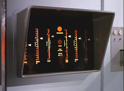
There are four “lanes”, one for each channel. In each lane, short lines representing the quantised pitch (on a semitone scale) scroll leftwards. The small triangles to their right move up and down to indicate the octave for that channel. Triggers (a vertical bar) and input voltages (a horizontal bar, left-going for negative voltages, right-going for positive) are indicated above each channel lane (replaced by a bit-pattern display when the sources are set to LFSR (Turing Machine) or logistic map, rather than external CV).
Tips
You can disable quantisation on each channel by setting the scale to Off. When in clocked mode (that is, Trigger source is set to TR1, TR2, TR3 or TR4), then that channel acts as a traditional sample-and-hold (S&H), without any voltage droop, of course. Thus, Quantermain can act as a quad S&H if you want. The only limitation is that the effective maximum sample rate is about 1 kHz, even if the clock/trigger signal you give it is at a higher frequency. This is because the ADCs are only read at an effective rate of about 1 kHz.
Disabling quantisation when using a Turing Machine, Logistic map, byte beats or integer sequence internal source allows the output for that channel to act as a semi-random modulation source.
Meta-Q
Meta-Q is a dual-channel quantiser that works similarly to Quantermain, except, of course, there are only two channels. It has also fewer internal CV sources (currently, only LFSR. See Copiermaschine/Quantermain for details).
- here is the default i/o mapping:
-
the main difference to Quantermain is that in Meta-Q, each channel comes with four editable scale ‘slots’. Each of these slots (=
scale #) can be mapped to any of the available preset and user scales and/or scale masks (via the main menu or scale editor). -
the four slots can then be sequenced by using either a clock signal (see the
seq modeparameter), or they can be modulated by using CV inputs CV2 and CV4 (see theCV aux.parameter). -
NB: TR2 and CV2 are hardcoded to service channel #1, TR4 and CV4 to service channel #2:
-
TR2 and TR4 can be used to cycle through either 2, 3, or 4 scale slots (=
seq modesettingsTR+1,TR+2,TR+3) -
setting the CV aux. parameter to
scl#(= scale #) allows modulation of the scale slot parameter with a CV signal applied to CV2 (channel #1) or CV4 (channel #2). -
alternatively, CV aux. can be routed to
root,mask(= scale mask),trns(= transpose/semitones), oroct(transpose/octaves).
-
-
when
trigger source= TR1 - TR4, the aux. outputs (C, D) simply pass through the main trigger signal, with adjustable pulse-width (--> pw); when set to continuous (cnt), the aux. output goes high if/when the note changes (= trigger-on-note-change). -
the aux. outputs can alternatively output a transposed copy of the main channel CV (aux.output =
copy), or output said CV, delayed by one clock (aux.output =asr).
Inputs and outputs
| I/O | Function | - |
|---|---|---|
| TR1 | clock input #1 | - |
| TR2 | scale sequencer clock #1 | - |
| TR3 | clock input #2 | - |
| TR4 | scale sequencer clock #2 | - |
| CV1 | sample in # 1 | - |
| CV2 | (mappable) | - |
| CV3 | sample in # 2 | - |
| CV4 | (mappable) | - |
| A, B | CV outputs #1, #2 | - |
| C, D | aux outputs #1, #2 (default to gate output) | - |
Available settings (per-channel)
| Setting | Meaning |
|---|---|
scale |
current scale |
scale # |
selected scale slot (#1 - #4) |
--> edit |
edit scale mask (for details see Quantermain and below) |
seq mode |
advance scale slots via trigger input (TR2 or TR4) |
root |
root note |
CV source |
sample input, internal/external (CV1 - CV4, LFSR) |
CV aux. |
aux CV input destination: scale #, root, transpose, octave, mask |
trigger source |
main trigger source: TR1 - TR4 , cnt+, cnt- (†) |
--> latency |
quantization latency (default: 0 = 60 us) |
octave |
offset in octaves |
transpose |
offset in semitones |
aux.output |
aux channel output: gate, copy, asr (††) |
--> pw |
pulse-width of triggers at C/D outputs (gate mode) |
--> aux +/- |
offset at C/D outputs (in octaves) (copy and asr modes) |
> LFSR length |
length of shift register (when in LFSR mode) |
> LFSR p |
probability of flipping (when in LFSR mode) |
> LFSR range |
output range (when in LFSR mode) |
> LFSR CV |
destination of CV1 resp. CV3 (when in LFSR mode) |
> LFSR TRIG |
aux channel output (when in LFSR mode): echo, lsb, chng: clock through, track LSB, and output on note-change |
- notes:
- (†)
cnt+andcnt-= continuous quantization; in this case, a gate applied toTR1resp.TR3will shift the pitch up (cnt+) or down (cnt-) by one octave. - (††)
copysimply duplicates the main channel output to the aux channel output.asrdoes the same, but delayed by one clock.
- (†)
Controls:
main menu
| Control | Function |
|---|---|
| Left encoder (turn) | select channel |
| Left encoder (press) | toggle channel |
| Left encoder (long press) | copy selected scale/mask to all channels/slots |
| Right encoder (turn) | Navigation mode: move up and down through the menu items. Edit mode: increase or decrease the value being edited |
| Right encoder (press) | Toggle between menu navigation (selection) mode and value editing mode |
| Right encoder (long press) | app selection menu |
| Up button | Transpose up: one octave (parameter menu) |
| Down button | Transpose down: one octave (parameter menu) |
| Up button (long press) | screensaver |
| Down button (long press) | reset scale mask |
scale editor
- works mostly the same (as in the other quantising modes). Notably, the
upanddownbuttons behave differently, to enable ‘offline’ editing of scales (rather than inverting the scale), as does the right encoder (= scale select).
| Control | Function |
|---|---|
| Left encoder (turn) | select note |
| Left encoder (press) | activate/de-active note |
| Right encoder (turn) | select scale |
| Right encoder (press) | exit editor |
| Up button | go to next scale slot (edit ‘offline’) |
| Down button | go to previous scale slot (edit ‘offline’) |
| Right encoder (long press) | – (app selection menu) |
| Up button long press | – (screensaver) |
Quadraturia
Quadraturia is a port of of the quadrature wavetable LFO that is available as the “Easter egg” in the Mutable Instruments Frames module. However, Quadraturia adds voltage control over three of the four LFO parameters (as well as CV control of frequency/rate of the LFO, as in Frames). Because the background ISR of o_C runs at 16.7KHz instead of 32KHz as in Frames, the behaviour of Quadraturia may not be identical to the Frames Easter egg, but it should be very close, and is nonetheless a very useful and flexible source of modulation voltages. For more details of how the Frames Easter egg LFO behaves, see the relevant section of the Frames Manual.
Internally, there are four LFOs (LFO1 to LFO4), with LFO2 to 4 running at some ratio of the (master) frequency of LFO1 (by default, that ratio is one, so all the LFOs run at the same frequency). The wave shape, phase of frequency modulation of LFO2 to 4 can be changed, relative to those parameters for LFO1, using the Shape spread, phase/frequency spread and coupling controls (see table below).
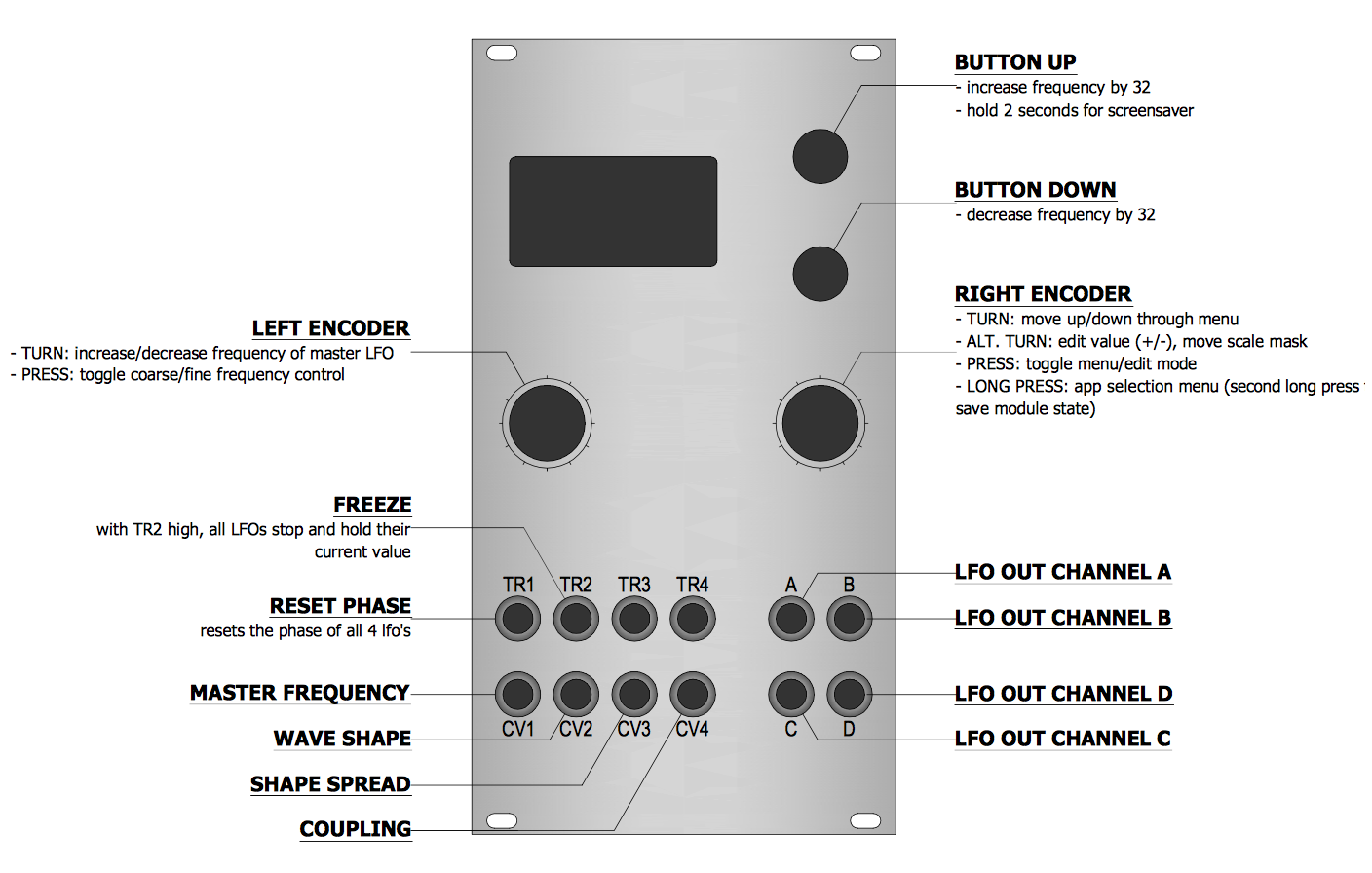
| I/O | Function |
|---|---|
| TR1 | Reset phase (all LFOs) |
| TR2 | Freeze (all LFOs stop in their tracks and hold current value while TR2 is high) |
| CV1 | Master frequency |
| CV2 | Wave shape |
| CV3 | Shape spread |
| CV4 | Coupling |
| A, B, C, D | LFO channel outputs |
Controls
| Control | Function |
|---|---|
| Left encoder (turn) | Increase or decrease frequency of master LFO |
| Left encoder (press) | Toggle frequency control between Coarse and Fine control. |
| Right encoder (turn) | Navigation mode: move up and down through the menu items. Edit mode: increase or decrease the value being edited. |
| Right encoder (press) | Toggle between menu navigation (selection) mode and value editing mode |
| Right encoder (long press) | App selection menu |
| Up button | Increment frequency by 32 |
| Down button | Decrement frequency by 32 |
Settings
| Setting | Meaning |
|---|---|
Coarse or Fine (frequency) |
Frequency, range is 0-255 for coarse adjustment, and each unit of the coarse adjustment is divided into 256 steps for fine adjustment |
Shape |
controls the shape of the primary waveform (LFO1), as shown in the preview waveform |
Shape spread |
sets the difference in wavetable position between each channel (and thus the differences in the wave shape for chennels B, C and D. |
Phase/frq spread |
sets the phase or frequency offset between each channel. Values greater than zero cause the phase to be offset incrementally in channels B, C and D wrt channel A. Values less than zero cause a progressive frequency shift (detune) across channels B, C and D wrt channel A. |
Coupling |
sets the degree of phase-modulation “bleed” between each successive channel. |
Output range |
sets the overall output range for all channels. The range of this settings goes from 0 (no output) to 230, which equates to a nominal output range from about -3.5V to +6V. By default, with the Offset setting (see below) at zero, the output range is asymmetric. By reducing the Output range and then setting a positive Offset, the output can be shifted so that it is unipolar or otherwise offset at the level desired. |
Offset |
shifts the output on all channels up or down by up to several volts. The range is -128 to 127, with a default of zero. Note that this is an internal offset and the absolute output voltage range is constrained by the hardware to about -3.5V to +6V. Nonetheless, by using it in conjunction with reduced settings of the Output range parameter, it is possible to make the output entirely unipolar, or even entirely negatively unipolar, if desired. Note that the Output value is added directly to the value sent to the DAC, and therefore positive or negative offsets (that is, non-zero offsets) without any reduction in the Output range setting will result in the 16-bit values sent to the DAC overflowing and wrapping around. This will cause waveform deformations, which may be useful or interesting. To remove any such wrap-around deformation, reduce the Output range setting when using non-zero offsets. If Output range and Offset are left at their defaults of 230 and zero respectively, no waveform deformation will occur. |
Freq range |
sets the frequency range for the quadrature LFOs, with self-explanatory settings of cosm (cosmological), geol (geological), glacial (glacial), snail, sloth, lazy (very lazy), lazy, vslow (very slow), slow, med (medium), fast and vfast (very fast). The faster settings extend into audio range. The slowest period for one cycle of the LFO on the cosm setting exceeds 18 hours. Note that Quadraturia does not, and is not intended to track 1V/octave. |
B freq ratio |
sets the frequency ratio at which LFO2 (channel B) runs wrt the master LFO (LFO1, channel A). The default is unity, so that it runs at the same frequency as channel A. Available ratios are 4/5, 2/3, 3/5, 1/2, 2/5, 1/3, 1/4, 1/5, 1/6, 1/7, 1/8, 1/9, 1/10, 1/11, 1/12, 1/13, 1/14, 1/15 and 1/16. |
C freq ratio |
does the same as B freq ratio, except for the channel C LFO. |
D freq ratio |
likewise |
B XOR A |
if enabled causes the 16 bits of the channel B LFO current value to be bit-wise XORed with the bits of the channel A LFO current value before being output on channel B. Available settings are Off, or 1 to 8, where the number refers to the number of bit of right-shift that are carried out before bit-XORing. bit-XORing can create digital noise at audio rates, but at slower modulation rates, all sorts of interesting “toothed” or other geometric patterns may emerge - but with very sharp transitions in amplitude. Try feeding it into the cut-off of a LPF (a technique shown in a Bastl video). |
C XOR A |
if enabled causes the 16 bits of the channel C LFO current value to be bit-wise XORed with the bits of the channel A LFO current value. |
D XOR A |
if enabled causes the 16 bits of the channel D LFO current value to be bit-wise XORed with the 16 bits of the channel A LFO current value. |
Screensaver display
The screen is divided into quadrants, each showing a rolling display of the output values on each of channels A to D.
Tips
-
To achieve the classic quadrature LFO patch (incremental 90° phase offset on outputs), set the phase/frq spread to +127.
-
Try mixing the some of the outputs with a DC-coupled mixer (such as the Mutable Instruments Shades or Links modules) in order to create even more complex waveforms.
Low-rents
Low-rents is a port of the Lorenz attractor modulation generator from the “Easter egg” in the Mutable Instruments Streams module, to which Rössler attractors have been added.
Two independent function generators are provided (referred to here as Generator 1 and Generator 2), with each generator calculating both the Lorenz and Rössler functions simultaneously, using the same phase accumulator, but with the rate/speed of each generator independently settable. Both the Lorenz and the Rössler functions output three values (x, y & z), and various combinations of these can be mapped to the four output channels. The chaotic strange attractors work best as slow modulation functions.
Note that the output voltage range of the o_C module is asymmetrical (about -3V to +6V) — because it was designed to process pitch CVs. Therefore the output of the Low-rents app is not centred about 0V.
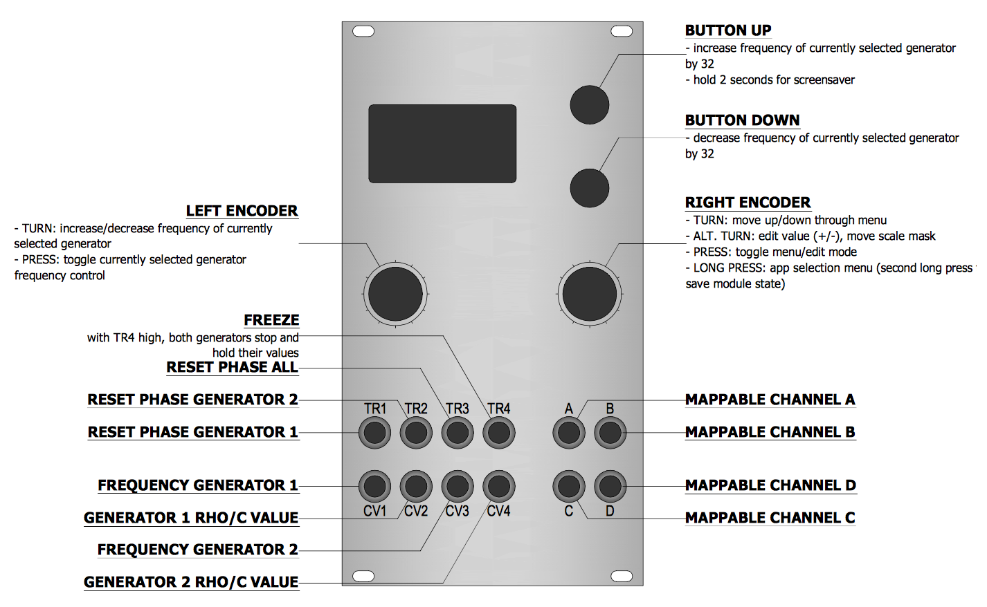
| I/O | Function |
|---|---|
| TR1 | Reset phase of generator 1 |
| TR2 | Reset phase of generator 2 |
| TR3 | Rest phase of both generators |
| TR4 | Freeze (both generators stop in their tracks and hold current value while TR4 is high) |
| CV1 | Frequency/speed of generator 1 |
| CV2 | Rho or c parameter for generator 1 |
| CV3 | Frequency/speed of generator 2 |
| CV4 | Rho or c parameter for generator 2 |
| A, B, C, D | Mappable outputs from the two generators (see table below) |
Controls
| Control | Function |
|---|---|
| Left encoder (turn) | Increase or decrease frequency of currently selected generator (1 or 2) |
| Left encoder (press) | Toggle currently selected generator frequency control |
| Right encoder (turn) | Navigation mode: move up and down through the menu items. Edit mode: increase or decrease the value being edited. |
| Right encoder (press) | Toggle between menu navigation (selection) mode and value editing mode |
| Right encoder (long press) | App selection menu |
| Up button | Increment frequency of currently selected generator by 32 |
| Down button | Decrement frequency of currently selected generator by 32 |
Settings
| Setting | Meaning |
|---|---|
Freq 1 |
Frequency/speed of generator 1, range is 0-255 |
Freq 2 |
Frequency/speed of generator 2, range is 0-255 |
Rho/c 1 |
Rho (for Lorenz attractor) or c (for the Rössler attractor) parameters for generator 1 |
Rho/c 2 |
Rho (for Lorenz attractor) or c (for the Rössler attractor) parameters for generator 2 |
out A |
output mapping for output A. Available choices shown in the table below. |
out B |
output mapping for output B. Available choices shown in the table below. |
out C |
output mapping for output C. Available choices shown in the table below. |
out D |
output mapping for output D. Available choices shown in the table below. |
| Output mapping value | Meaning |
|---|---|
Lx1 |
Generator 1 Lorenz attractor x value |
Ly1 |
Generator 1 Lorenz attractor y value |
Lz1 |
Generator 1 Lorenz attractor z value |
Lx2 |
Generator 2 Lorenz attractor x value |
Ly2 |
Generator 2 Lorenz attractor y value |
Lz2 |
Generator 2 Lorenz attractor z value |
Rx1 |
Generator 1 Rössler attractor x value |
Ry1 |
Generator 1 Rössler attractor y value |
Rz1 |
Generator 1 Rössler attractor z value |
Rx2 |
Generator 2 Rössler attractor x value |
Ry2 |
Generator 2 Rössler attractor y value |
Rz2 |
Generator 2 Rössler attractor z value |
Lx1+Rx1 |
Sum of Generator 1 Lorenz attractor x value and Generator 1 Rössler attractor x value |
Lx1+Rz1 |
Sum of Generator 1 Lorenz attractor x value and Generator 1 Rössler attractor z value |
Lx1+Ly2 |
Sum of Generator 1 Lorenz attractor x value and Generator 2 Lorenz attractor y value |
Lx1+Lz2 |
Sum of Generator 1 Lorenz attractor x value and Generator 2 Lorenz attractor z value |
Lx1+Rx2 |
Sum of Generator 1 Lorenz attractor x value and Generator 2 Rössler attractor x value |
Lx1+Rz2 |
Sum of Generator 1 Lorenz attractor x value and Generator 2 Rössler attractor z value |
Lx1xLy1 |
Bit-wise XOR of Generator 1 Lorenz attractor x value and Generator 1 Lorenz attractor y value |
Lx1xLx2 |
Bit-wise XOR of Generator 1 Lorenz attractor x value and Generator 2 Lorenz attractor x value |
Lx1xRx1 |
Bit-wise XOR of Generator 1 Lorenz attractor x value and Generator 1 Rössler attractor x value |
Lx1xRx2 |
Bit-wise XOR of Generator 1 Lorenz attractor x value and Generator 2 Rössler attractor x value |
The Rho and c parameters for the Lorenz and Rössler attractors respectively determine the degree of variability in the chaotic generator system. Note that the values have been constrained so that the functions do not collapse, but some combinations of extreme settings may cause the generator functions to collapse completely. If this happens, change the Rho/c setting and send a rest pulse to the relevant trigger input to reset the function generator.
Screensaver display
The screensaver show the A and B outputs in a vectorscope (X/Y) display on the left half of the screen, and the C and D outputs as a vectorscope display on the right half of the screen.
Tips
If you have an oscilloscope capable of displaying X/Y (vectorscope) signals, try patching pairs of the x, y and z outputs from either type of generator into it to observe the classic strange attractor patterns.
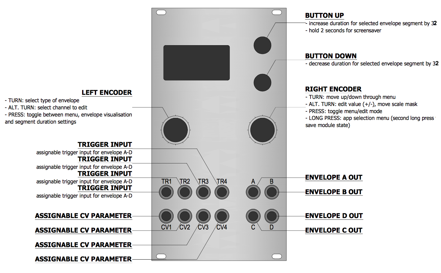
Piqued
Piqued is a a port of the envelope generator function from the open-source Mutable Instruments Peaks module. Piqued provides four independently-triggerable envelopes on output channels A to D, with independently mappable voltage-control via the CV1 to CV4 inputs over envelope duration parameters for each segment of each envelope. (v1.1 or later: Voltage control over the Euclidean trigger filter parameters and the trigger delay time is also possible — see below.) Triggers for each of the four envelopes can also be mapped from any of the four trigger inputs (TR1 to TR4). Segment shape (curves) can be set for each segment of each of the four envelopes. A variety of envelope types are available, also independently settable for each envelope, including repeating (looping) envelope types. The shape of each envelope can be visualised while setting parameters. There is also a “Euclidean trigger filter” included, which turns the Piqued app into a quad-channel Euclidean polyrhythm generator, that can output envelopes, not just gate/trigger signals. See the o_C videos page for some demonstrations of Piqued.
Controls
Piqued presents quite a rich UI (user interface), which is harder to describe in words than it is to use. The following explanations should make sense as soon as you see the UI in action. Once experienced, the interface becomes quite intuitive, we think.
| Control | Function |
|---|---|
| Left encoder (turn) | In menu settings mode, elect the type of envelope. In envelope visualisation mode, select channel A to D to edit (all channels always active) |
| Left encoder (press) | Toggle between menu settings and envelope visualisation and segment duration settings. |
| Right encoder (turn) | Navigation mode: move up and down through the menu items (when in menu setting mode), or move back and forth between envelope segments (envelope visualisation/segment duration setting mode). Edit mode: increase or decrease the value being edited (segment durations when in envelope visualisation mode). |
| Right encoder (press) | Toggle between menu navigation (selection)/envelope segment selection mode and value editing mode |
| Right encoder (long press) | App selection menu |
| Up button | Increase duration for currently selected envelope segment for currently displayed envelope generator (A to D) by 32 (when in envelope visualisation mode only) |
| Down button | Decrease duration for currently selected envelope segment for currently displayed envelope generator (A to D) by 32 (when in envelope visualisation mode only) |
Available settings (per-channel)
| Setting | Meaning |
|---|---|
| (envelope type) | the type of envelope (segment nomenclature is standard: A=attack, D=decay, S=sustain (level) and R=release). Available envelope types are described in the table below. |
Trigger input |
specifies which trigger/gate input, TR1 to TR4, is used to trigger or gate the envelope on the channel currently displayed. |
Tr delay mode |
sets the mode for the trigger delay. See notes below.If enabled, the trigger delay will postpone the “firing” of the envelope (that is, the commencement of the attack segment of the envelope) for the time set by Tr delay msecs and Tr delay secs (see below). Available trigger delay modes are Off, Queue and Ring. Queue means that subsequent triggers received while a delay period is active are added to a queue for later action, up to a maximum queue depth set by the Tr delay count setting (maximum 32). Further triggers during the delay period are ignored until the number of queued triggers falls below the value set by Tr delay count. Ring is similar except that triggers received after the queue is full will replace the final trigger in the queue. |
Tr delay count |
sets the number of trigger delays that will be stored or buffered for later processing. |
Tr delay msecs |
trigger delay in milliseconds (range 0 to 999 milliseconds). If you set a trigger delay of greater than zero, then the envelope for that channel will not “fire” (commence its attack segment) until the specified delay has elapsed. The delay in milliseconds and the delay in seconds are added together, allowing very fine control over the delay. The “countdown” time for the delayed trigger is shown as a fall bar on the righthand side of the trigger indicator for that channel (at the top of the display). |
Tr delay secs |
trigger delay in seconds (range 0 to 64 seconds) — see Tr delay msecs above. |
Eucl length |
sets the length of the Euclidean pattern (range 2 to 32 in “beats”, where each beat is a received trigger/gate pulse) used to filter triggers for that channel. For a detailed explanation of Euclidean patterns and their use in rhythm generation, see this paper by Godfried Toussaint, or for a brief explanation, see this presentation. Eucl length defaults to Off, which means there is no filtering of triggers. |
Eucl fill |
sets the number of beats in the pattern that let triggers through to “fire” the envelope. If the fill number is equal to or greater than the Euclidean pattern length number, then every incoming trigger will pass the Euclidean filter and fire the envelope for that channel. If the fill number is zero, then none shall pass. |
Eucl offset |
sets the offset (or more accurately, the rotation) of the Euclidean pattern. The combination of pattern length (Eucl length) and number of active beats (Eucl fill) within that pattern length uniquely determines the Euclidean pattern, using the Bjorklund algorithm. For example, if Eucl length is set to 8 and Eucl fill is set to 5, and Eucla offset is set to the default of 0, then the pattern will be 10110110, where 1 is an active beat (triggers are allowed to pass) and 0 is inactive (triggers are blocked). By setting Eucl offset to 1, the pattern becomes 01101101, if set to 2 the pattern becomes 11011010 and so on. |
CV1 -> |
sets the mapping from the CV1 input. The value on CV1 can be ignored (None) or sent to control the duration of one of: Att(ack), Dec(ay), Sus(tain) (level, not duration) and Rel(ease), or it can be set to control the Euclidean trigger filter parameters: Eleng (Euclidean pattern length), Efill (Euclidean pattern fill, Eoffs (Euclidean pattern offset/rotation), or the trigger delay time (Delay), or it can be set to control overall envelope amplitude (Ampl). Note that when set to Eleng or Efill, negative voltages can be used to block all triggers. The input CV values are added to whatever is set for the duration/level or Euclidean parameters or trigger delay time or overall amplitude level via the menu settings. |
CV2 -> |
same as CV1 ->, but for the CV2 input |
CV3 -> |
same as CV1 ->, but for the CV3 input |
CV4 -> |
same as CV1 ->, but for the CV4 input |
Attack reset |
specifies the behaviour when a new trigger or gate (i.e. rising edge of the gate) is received while the attack segment of an envelope is still in progress. The available values are None (new triggers are ignored while the attack segment is active), SP (reset Segment and Phase, which resets the segment to attack, which is was anyway, and restarts the segment at phase zero, but retains the current envelope level when the trigger was received, thus avoiding sudden jumps in envelope level and consequent audible clicks or pops, as far as possible), SLP (reset Segment, Level and Phase — this also resets the level back to zero — this may result in clicks or pops, as the change in level is instantaneous), SL (reset Segment and Level - this resets the level but not the phase - this also results in sudden level jumps, but of a different type), P (reset Phase only, which for the attack segment is the same as resetting both segment to attack and resetting phase). The default is None, and in general, the expected behaviour will probably result by setting it to None or SP. The other options are offered to permit experimentation. A dual-channel oscilloscope which allows simultaneous visualisation of the trigger pulses and the resulting envelope shapes is very useful in working out the exact behaviour, which can be complex when the period of a train of triggers is about the same as the period for the envelope being triggered. |
DecRel reset |
specifies the behaviour when a new trigger or gate (i.e. rising edge of the gate) is received while the decay or release segments of an envelope are still in progress. The available values are None (new triggers are ignored while the decay or release segment is active), SP (reset Segment and Phase, which resets the segment to attack and restarts the segment at phase zero, but retains the current envelope level when the trigger was received, thus avoiding sudden jumps in envelope level and consequent audible clicks or pops, as far as possible), SLP (reset Segment, Level and Phase - this also resets the level back to zero - this may result in clicks or pops, as the change in level is instantaneous), SL (reset Segment and Level - this resets the level but not the phase - this also results in sudden level jumps, but of a different type), P (reset Phase only, which doesn’t restart a new attack segment, instead, the current decay or release segment is restarted at phase 0 but at the current level, effectively extending it). The default is SP, and in general, the expected behaviour will probably result by setting it to None or SP. The other options are offered to permit experimentation. A dual-channel oscilloscope which allows simultaneous visualisation of the trigger pulses and the resulting envelope shapes is very useful in working out the exact behaviour, which can be complex when the period of a train of triggers is about the same as the period for the envelope being triggered. |
Gate high |
when set to Yes, forces the trigger/gate to high. This is useful when using the looping envelope types, which then just loop continuously, regardless of what is happen on their trigger/gate input, and thus they act as LFOs. |
Attack shape |
sets the shape of the attack segment for the currently displayed envelope. Available shapes are listed in the table below. |
Decay shape |
sets the shape of the decay segment for the currently displayed envelope. Available shapes are listed in the table below. |
Release shape |
sets the shape of the release segment for the currently displayed envelope. Available shapes are listed in the table below. |
Attack mult |
sets the duration multiplier for the attack segment(s). Range is 1 to 8192, which allows for very, very slow envelopes if desired. |
Decay mult |
sets the duration multiplier for the decay segment. Range is 1 to 8192. Note that you can still have a short attack but a very, very long decay or release, if desired, by setting different duration multipliers for each of attack, decay and release. |
Release mult |
sets the duration multiplier for the release segment. Range is 1 to 8192. |
Amplitude |
sets the overall amplitude for the envelope, from 0 (no amplitude) to 127 (full range). Defaults to 127. Use it in conjunction with voltage control overall envelope amplitude to dynamically vary the envelope amplitude (that is, the maximum envelope level). See also the related Sampled Ampl setting, immediately below. |
Sampled Ampl |
toggles whether the overall amplitude value for the envelope is set continuously, or whether the overall amplitude value is sampled when a new trigger/gate is received and then remains at that sampled value until a new trigger/gate is received. It defaults to off. |
| Envelope type | Description |
|---|---|
AD |
Attack-Decay: the attack segment commences on receipt of a trigger or on the rising edge of a gate signal, and the decay segment follows immediately after the attack segment has reached its peak, regardless of whether the gate or trigger signal is still high. |
ADSR |
Attack-Decay-Sustain-Release: just like every other ADSR envelope |
ADR |
Attack-Decay-Release: the attack segment commences on receipt of a trigger or on the rising edge of a gate signal, and the decay segment follows immediately after the attack segment has reached its peak. The sustain level is an inflection point for the decay - when the decay reaches the sustain level, the release segment immediately commences, regardless of whether the gate or trigger signal is still high. See the Tips section below on how to use the ADR mode as an AHR/AHD (attack-hold-release or attack-hold-decay) envelope generator with trigger signals. |
ASR |
Attack-Sustain-Release: the attack segment commences on receipt of a trigger or on the rising edge of a gate signal, and the envelope stays at maximum level for as long as the gate input for it remains high (sustain), and then commences the release segment as soon as the gate signal goes low. |
ADSAR |
is like an ADSR envelope, except that the attack segment re-triggers as soon as the sustain segment is finished, before proceeding to the release segment. |
ADAR |
is like the ADR envelope, except that the attack segment re-triggers as soon as the decay segment has finished, before going into the release segment. |
AD loop |
is like the AD envelope, except that it automatically re-triggers for as long as the trigger/gate input for it is high (see also the Gate high setting) |
ADR loop |
is like the ADR envelope, except that it automatically re-triggers for as long as the trigger/gate input for it is high (see also the Gate high setting) |
ADAR loop |
is like the ADAR envelope, except that it automatically re-triggers for as long as the trigger/gate input for it is high (see also the Gate high setting) |
| Segment shape | Description |
|---|---|
Lin |
Linear (a straight line, equation x = t where t is time) |
Exp |
Exponential (equation x = 1 - e-4t) |
Quart |
Quartic (equation x = t3.32) |
Sine |
half a sine wave (equation x = sin(8 * pi * t) ) |
Ledge |
almost a square wave, but with rounded corners, when used for attack, gives an immediate (punchy) rise, then a plateau. When used for decay or release, it has a plateau before falling. |
Cliff |
similar to Ledge, but when used for attack, has a delay before rising, when used for decay or release, it falls immediately. |
Gate (v1.1) |
is used when gate outputs are desired. The value rises immediately to maximum in the attack segment, and the value falls immediately to minimum in the decay and release segments. In other words, a pulse is output. |
BgDip |
Big dipper - has one large bump on the way up or down. |
MeDip |
Medium dipper - has a medium sized dip on the way up or down. |
LtDip |
Little dipper - has a little dip (more a ledge) on the way up or down. |
Wiggl |
Wiggles - lots of wiggles on the way up or down. |
Inputs and outputs
Trigger input and CV1 to CV4 are mappable per-channel via the menu, as described above. Outputs for envelopes A to D appear on outputs A to D respectively.
Screensaver display
The screen is divided into quadrants, each showing a rolling display of the output values on each of channels A to D. Superimposed on this rolling value line is a representation of the envelope for that channel, as it progresses through its segments.
Tips and tricks
- the ADR mode can also be used as an AHR (attack-hold-release, sometimes also called AHD (attack-hold-decay)) envelope generator. AHR envelope are useful when you want to generate an envelope with a flat sustain period, which usually requires a gate input with some duration. If you only have trigger signals, that is, short pulses, then you can create an AHR envelope by choosing ADR mode, and setting the sustain inflection point to 255 (maximum). By doing that, the decay segment falls from maximum value to… maximum value - in other words, it’s flat! The decay segment time/duration then sets the hold duration after a trigger is received. Also try setting the sustain level in ADR mode to something a little bit less than 255 (say 230), and set the decay shape to Wiggle. Now you have an AHR envelope with a wiggly and slightly downsloping plateau segment. Several variations on this theme are possible.
Sequins
Sequins is a basic, dual-channel sequencer. The app provides four 16-step sequences per channel, and CV-control over various channel parameters, including scale mask, octave, pulsewidth, clock multiplication and division. The four sequences can be chained in various ways, providing sequences from 4 to up to 64 notes. The sequence data is stored along with the other settings (whenever settings are saved).
- Here’s the default mapping, the CV inputs can be freely assigned:
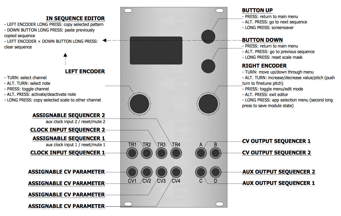
-
Channel #2 has the symmetrical layout, mapped to outputs B (pitch) and D (trig/gate) (highlighted yellow).
- the sequence editor works similarly to the scale editor in the quantizer modes:
- in the main menu, select which sequence to edit by adjusting the
sequence #parameter. -
then right-click on the item displayed right below (
--> edit) to open the sequence-editor:- mute/unmute notes by clicking the left encoder.
- adjust the sequence length by pointing the cursor to the far right, then turn the right encoder.
- (simultaneously push down the left encoder to also mute the steps that are being added while expanding the sequence).
- to adjust the pitch, simply move the cursor to a given slot, then turn the right encoder: this will increase or decrease the pitch in semitones (= step size:
128). - to fine-tune the pitch (= step size:
1), hold down the left encoder while turning the right encoder (the effect this has will depend on the chosen scale). - note: the number displayed when adjusting the note values is the actual (pre-quantization) DAC code (that’s far from ideal, i know …). details on what those numbers mean can be found here.
- in the sequence-editor, you can use the up/down buttons to select which sequence to edit (
#1-#4). (this makes it possible to edit sequences ‘offline’, ie make adjustments to, say, sequence #2 while sequence #1 is playing). - copy+paste: in the sequence-editor, long-press the left encoder to copy the selected sequence. select a different sequence slot, then long-press the down button to paste it into that slot. copy+paste works across channels. (note: once copied (or pasted), sequence data will be stored in a temporary buffer for about 15 seconds, after which it’ll expire.)
- in the main menu, select which sequence to edit by adjusting the
-
the
playmodeanddirectionsettings offer various ways of moving through the sequence(s):-(default): advance by trigger, using the chosen sequence and direction settings.SEQ+1 - SEQ+3: ditto, but cycling through 2, 3, or 4 adjacent sequences (= allows up to 64 notes).TR+1 - TR+3: ditto, but jumps to the next sequence only if/when a trigger is received at the aux. trigger inputs.S+H#1 - S+H#4: CV-address, when triggered (sample and hold).CV#1 - CV#4: CV-address, free-running.
-
note: when in CV-address mode, the
CV adr. rangesetting adjusts the resolution of the chosen input (CV1-CV4), relative to the length of the sequence (ie, you’ll either need5Vor10Vto move through the entire span of the sequence). - the secondary/aux. clock inputs (TR2, TR4) can be used to either cycle through the sequences (see above), or they can be selected as a reset/mute signal (
reset/mute). the options are:RST2,RST4(reset) and=HI2,=LO2,=HI4, and=LO4(mute when aux. clock goes high, respectively low.)
Inputs and outputs
| I/O | Function | - |
|---|---|---|
| TR1 | clock input #1 | - |
| TR2 | aux clock input #1 / reset/mute #1 | - |
| TR3 | clock input #2 | - |
| TR4 | aux clock input #2 / reset/mute #2 | - |
| CV1 | (mappable) | - |
| CV2 | (mappable) | - |
| CV3 | (mappable) | - |
| CV4 | (mappable) | - |
| A, B | CV outputs #1, #2 | - |
| C, D | aux outputs #1, #2 (default to gate output) | - |
Available settings (per-channel)
| Setting | Meaning |
|---|---|
scale |
current scale |
--> edit |
edit scale mask (for details see here) |
sequence # |
select sequence #1 - #4 |
--> edit |
edit sequence |
playmode |
chain sequences (SEQ+x), advance by trigger (TR+x), or CV-address |
direction |
forward, reverse, pendulum1, pendulum2 (repeat first/last), random |
mult/div |
set clock multiplier / divider |
mode |
aux channel output: gate, copy |
CV adr. range |
toggle 5V/10V (in CV address mode) |
--> pw |
pulse-width of triggers at C/D outputs (in gate aux. mode) |
--> aux +/- |
offset at C/D outputs (in octaves) (in copy aux. mode) |
reset/mute |
select reset/mute source (mute being more like ‘pause’) |
clock src |
choose channel clock source (TR1 or TR3) |
Controls
main menu
| Control | Function |
|---|---|
| Left encoder (turn) | select channel |
| Left encoder (press) | re-sync channels (reset) |
| Left encoder (long press) | copy selected scale to other channel |
| Right encoder (turn) | Navigation mode: move up and down through the menu items. Edit mode: increase or decrease the value being edited |
| Right encoder (press) | Toggle between menu navigation (selection) mode and value editing mode |
| Right encoder (long press) | app selection menu |
| Up button | Transpose up: one octave (parameter menu) |
| Down button | Transpose down: one octave (parameter menu) |
| Up button (long press) | screensaver |
| Down button (long press) | CV menu |
CV menu
- enter the CV menu by holding down the down button for > 2 seconds:
- use the right encoder to assign CV input channels 1-4 to a channel parameter (currently available parameters are:
transposition(in octaves),scale mask,sequence number(1-4),pulsewidth, andmultiplier/divisor. - return to the main menu by either pressing the up or down buttons, or by moving the cursor to an empty field and then pressing the right encoder button.
- clear all mappings (per channel) by long-pressing the down button (in CV menu)
- use the right encoder to assign CV input channels 1-4 to a channel parameter (currently available parameters are:
| Control | Function |
|---|---|
| Left encoder (turn) | select channel |
| Left encoder (press) | re-sync channels (reset) |
| Left encoder (long press) | copy selected scale to other channel |
| Right encoder (turn) | Navigation mode: move up and down through the menu items. Edit mode: increase or decrease the value being edited |
| Right encoder (press) | toggle editing mode, if applicable; return to main menu otherwise |
| Right encoder (long press) | app selection menu |
| Up button | return to main menu |
| Down button | return to main menu |
| Up button (long press) | screensaver |
| Down button (long press) | clear CV mappings |
sequence editor
| Control | Function |
|---|---|
| Left encoder (turn) | select step |
| Left encoder (press) | activate/de-active step |
| Right encoder (turn) | 1) adjust pitch in semitones; push left encoder switch while turning to fine-tune. 2) adjust sequence length by pointing the cursor to the far right, then turn; push left encoder switch while turning to also clear the sequence mask (when expanding the pattern) |
| Right encoder (press) | exit editor |
| Up button | go to next sequence (edit ‘offline’) |
| Down button | go to previous sequence (edit ‘offline’) |
| Left encoder (long press) | copy selected pattern |
| Down button long press | paste previously copied sequence |
| Down button and Left encoder long press | clear sequence (including pitch data) |
| Right encoder (long press) | – (app selection menu) |
| Up button long press | – (screensaver) |
Dialectic Ping Pong
Dialectic Ping Pong is a port of the bouncing ball envelope generators from the Mutable Instruments Peaks module source code (these are not exposed in the official Peaks firmware, but are available on Peaks with the Dead Man’s Catch alternative firmware installed). These generators implement a simple but effective simulation of the physics of a ball that is thrown into the air with a certain velocity, from a certain height, and which then returns to Earth (or a planet of your choice) under the influence of (configurable) gravity, and then bounces (with a settable “bounce loss” simulating how hard the ball is pumped up, if it is a basketball), before being pulled back to Earth and bouncing again, and so on.
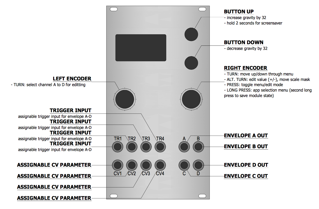
Controls
| Control | Function |
|---|---|
| Left encoder (turn) | Select channel A to D to edit (all channels always active) |
| Right encoder (turn) | Navigation mode: move up and down through the menu items. Edit mode: increase or decrease the value being edited. |
| Right encoder (press) | Toggle between menu navigation (selection) mode and value editing mode |
| Right encoder (long press) | App selection menu |
| Up button | Increase gravity by 32 |
| Down button | Decrease gravity by 32 |
Available settings (per-channel)
| Setting | Meaning |
|---|---|
Gravity |
g, the acceleration due to gravity, from 0 (no gravity) to 255 (gravity on a massive alien planet) |
Bounce loss |
The amount of energy lost by the ball at each bounce (0 to 255). Higher values act like a deflated basketball. |
Amplitude |
Initial amplitude (height) of the ball when the envelope is triggered, 0 to 255. |
Velocity |
Initial velocity of the ball when the envelope is triggered - the size of the kick or impulse imparted to the ball, if you like. Note that high values will cause the ball to bounce off the roof of the gymnasium that houses these envelopes. |
Trigger input |
Trigger input source (TR1 to TR4) for the current channel |
CV1 -> |
Mapping of the CV1 input to a parameter for the selected channel. Values are “off”, “grav” (gravity), “bnce” (bounce loss), “ampl” (initial amplitude), and “vel” (initial velocity). |
CV2 -> |
As for CV1->, but for CV2. |
CV3 -> |
As for CV1->, but for CV3. |
CV4 -> |
As for CV1->, but for CV4. |
Hard reset |
If set to on, the envelope will instantly restart at the currently set initial amplitude, rather than starting from the height that the ball happens to be at the time when the trigger is received. |
Inputs and outputs
Trigger input and CV1 to CV4 are mappable per-channel via the menu. Outputs for channels A to D appear on outputs A to D respectively.
Screensaver display
The screen is divided into quadrants, each showing a rolling display of the output values on each of channels A to D.
Viznutcracker, sweet!
This is a experimental implementation of several bytebeats signal generators. “bytebeats” are equations (actually, recursive functions), expressed usually as a single line of programme code, typically involving various bit-level operators, which when evaluated with an incrementing phase value at audio rates produce all manner of harsh digital noises, some of which sound musical, or at least, interesting. bytebeats were first described in 2011 by viznut (aka Ville-Matias Heikkilä).
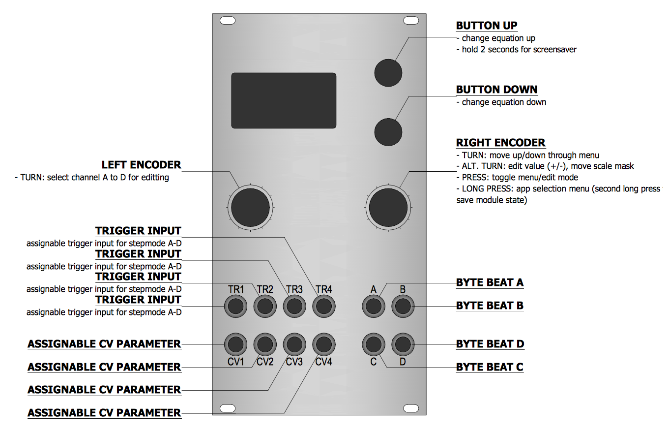
The output, if used as an audio signal, usually needs to be fairly heavily filtered through a low-pass filter to remove at least some of the unpleasant digital “screech” due to high-frequency aliasing and other effects which are characteristics of bytebeats. This digital aliasing is a fundamental characteristic of the way bytebeats work, and isn’t due to any hardware limitations of the o_C module.
The Viznutcracker, sweet! app current provides access to 8 different byte beat equations, although it is anticipated that more will be added in further versions. The app provides four independent byte beat generators, on channels A to D, which all run independently. The equation, speed/frequency and three equation parameter values (p0, p1 and p2) can be set via the menus and/or voltage-controlled for each generator via mappable CV inputs.
Perhaps uniquely amongst byte beat generator modules, the Viznutcracker, sweet! apps permits the byte beat generators to be run at very slow rates, and because the o_C module outputs are DC-coupled, they can therefore be used as sources of stepped control voltages. For example, the outputs can be fed into a quantiser (such as another o_C module) to create potentially interesting pitch sequences (possibly even melodies…). Furthermore, the app allows each byte beat equation to be incremented by an external clock/trigger input, so that these stepped voltages can be generated in synchrony with other external processes.
Available settings (per-channel)
| Setting | Meaning |
|---|---|
Equation |
Byte beat equation (see table below) |
Speed |
0 to 255. 255 equates to a 16.7 kHz sample rate (i.e. the phase accumulator advances 16,666 times per second). There is a rough quadratic scaling of lower rates, meaning that 0 is quite slow. |
Pitch |
1 to 255. This is a very rough pitch setting, which behaves differently with each equation. Increasing values of Pitch will increase the pitch (frequency) of some elements of the equation output, but not necessarily all components, so it may not sound like a normal pitch increase or decrease. However, its effect does sound different to the Speed parameter. (shrugs shoulders) |
Parameter 0 |
The first adjustable parameter in the chosen equation. Range 0 to 255, but some parameter settings in some equations do not produce any output, or do not produce output for all values of the phase accumulator (be patient!) |
Parameter 1 |
ditto for the second adjustable parameter in the equation |
Parameter 2 |
ditto for the third adjustable parameter in the equation |
Loop mode |
Enables loop mode, in which the phase accumulator is constrained to loop between specific start and end values, instead of between 0 and 4,294,967,296. |
Loop begin ++ |
Coarse loop begin point, range 0-255 |
Loop begin + |
Medium loop begin point, range 0-255 |
Loop begin |
Fine loop begin point, range 0 - 255 |
Loop end ++ |
Coarse loop end point, range 0-255 |
Loop end + |
Medium loop end point, range 0-255 |
Loop end |
Fine loop end point, range 0 - 255 |
Trigger input |
Specified which of the 4 trigger inputs (TR1 to TR4) is used for the trigger input for Step mode, or when Step Mode is off, which trigger input is used to reset the phase accumulator for that channel. |
Step mode |
When set to on, the phase accumulator is incremented when a trigger or clock pulse is received on the digital (trigger) input specified by the Trigger input setting. When set to off, a trigger (or rising edge of a pulse or clock) received on the trigger input specified by the Trigger Input setting will reset the phase accumulator (the t variable in byte beat equations), which has the effect of resetting the byte beats “tune” or “melody” back to its beginning, or back to the start of the loop start point if loop mode is enabled. |
CV1 -> |
specifies which parameter CV1 is mapped to for this channel. Choices are off, eqn, spd, p0, p1, p2, beg++, beg, end++, end and pitch. |
CV2 -> |
ditto for CV2 |
CV3 -> |
ditto for CV3 |
CV4 -> |
ditto for CV4 |
| Equation name | Source of equation |
|---|---|
hope |
“atmospheric, hopeful” via royal paw |
love |
the equation by stephth via here at 3:38 |
life |
the second equation listed here |
age |
“Arp rotator” via Microbe Modular Equation Composer Ptah bank |
clysm |
“BitWiz Transplant” via Microbe Modular Equation Composer Ptah bank |
monk |
“Vocaliser” via Microbe Modular Equation Composer Khepri bank |
NERV |
“Chewie” via Microbe Modular Equation Composer Khepri bank |
Trurl |
“Tinbot” via Microbe Modular Equation Composer Sobek bank |
Pirx |
“My Loud Friend” via Microbe Modular Equation Composer Ptah bank |
Snaut |
"”A bit high-frequency, but keeper anyhow” via Microbe Modular Equation Composer Khepri bank |
Hari |
“The Signs” via Microbe Modular Equation Composer Ptah bank |
Kris |
“Light Reactor” via Microbe Modular Equation Composer Ptah bank |
Tichy |
“Alpha” via Microbe Modular Equation Composer Khepri bank |
Bregg |
“Hooks” via Microbe Modular Equation Composer Khepri bank |
Avon |
“Widerange” via Microbe Modular Equation Composer Khepri bank |
Orac |
“Abducted” via Microbe Modular Equation Composer Ptah bank |
Screensaver display
Tips
-
as noted above, use the byte beat generators at very slow rates to generate DC control voltages. Feed these to a quantiser to produced pitch sequences, or pass them through a portamento or slew-limiting module to create interesting smooth modulation signals, or use them as-is, to modulate filters etc.
-
process the byte beats outputs running at audio rates through a low-pass or shelf filter to remove some of the high-pitched screech
-
process the output through band-pass filters (such as the Mutable Instruments Shelves filter), or other complex filtering arrangements subject to slow modulation (by another o_C module, perhaps)
-
process the output through a VCA and/or filter with a percussive envelope to produce interesting, well, percussive sounds. Use the same trigger or gate signal used to fire the envelopes also reset the phase on the byte beat generator. Use slow modulation to slowly vary the frequency/rate, and/or to “scrub” loop start and end points in order to vary the nature of the percussive sound.
References
References is a simple utility app which outputs fixed reference voltages. These are handy when calibrating other modules, such as VCOs.
Note that unlike all the other apps, the settings for references are not saved and will revert to the defaults each time the module is powered on. This is to save EEPROM storage space — saved settings were not regarded as critical for this app.
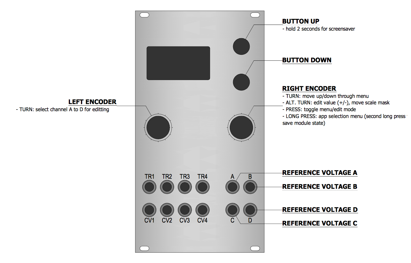
Controls
| Control | Function |
|---|---|
| Left encoder (turn) | Select channel A to D to edit (all channels always active) |
| Right encoder (turn) | Navigation mode: move up and down through the menu items. Edit mode: increase or decrease the value being edited. |
| Right encoder (press) | Toggle between menu navigation (selection) mode and value editing mode |
| Right encoder (long press) | App selection menu |
| Up button | |
| Down button |
Available settings (per-channel)
| Setting | Meaning |
|---|---|
Octave |
sets the octave range. Note that the octave numbering is such that C for octave 0 is 0V, C for octave 1 is 1V and so on. |
Semitone |
sets the semitone offset within each octave range. One semitone increment is 83.33mV. |
Mod range oct |
sets the number of octaves to automatically jump up or down. This can be useful when adjusting trimpots on VCOs. |
Mod rate (s) |
sets the rate (as a period in seconds) at which the reference voltage jumps up or down by the number of octaves set by Mod range oct. |
Inputs and outputs
No inputs are used. Reference voltages for channels A to D appear on outputs A to D respectively.
Screensaver display
The screen is divided into four channel lanes (columns), with the same layout as the Quantermain screensaver, except that the output voltage (rounded to the nearest millivolt) is shown as the top of each lane (column). Note that the minus signs for negative voltages are quite small due to the limited display space, and can be quite hard to see.
Firmware CHANGELOG
Known Issues
- sample rate: limited because DAC and OLED sit on the same data bus. for its (originally) intended purpose — as a module that quantizes/generates pitch CVs — the (resulting) 16.6 KHz DAC update rate is not a problem; in fact, it’s pretty good, hence the low latency (~60us). however, a 16.6 KHz update rate means that audible digital aliasing is present when the output is used as an audio source — which is why the only app intended as an audio source is Viznutcracker, sweet!, ie the byte beat generator, in which case audio quality isn’t a huge priority. That said, several of the other apps can produce signals in the audio range, but you may need to use them with a low-pass filter to remove some of the aliasing noise. Anyway, just be aware that o_C is intended to be used as a pitch CV generator, and as a slow modulation CV source, not as audio oscillator or audio signal generator.
- In theory, some of the digital aliasing may “bleed through” into the audio domain even when the o_C is used as a modulation CV source (eg as an envelope generator or LFO modulating a VCF cut-off or VCA gain). We have not found that to be a problem in practice, but if it does become apparent, then you can always interpose a low-pass filter between the o_C and whatever is being modulated. WMD make a module exactly for this purpose: the Quad Anti-aliasing Filter (QAAF). However, this is unlikely to be required.
- output range: asymmetrical (-3V/+6V), as a concession to typical pitch voltage ranges (re: quantizer). when used as an LFO (that is, the Quadraturia app), the waveform is thus not symmetrically bipolar. This can be corrected by adding -1.5V to each output, so that the output range is shifted from -3V to +6V, to -4.5V to +4.5V. The Mutable Instruments Shades module is excellent for doing such level shifting (and voltage scaling), but there are many other utility modules which can do the same. The Lorenz and Rössler functions output by the Low-rents app are similarly asymmetrical — they also range from -3V to +6V, due to the hardware design of o_C. (note: in v1.2, output offset and attenuation parameters were added to Quadraturia to permit unipolar output, albeit with reduced peak-to-peak amplitude). alternatively, you could mod the output stage.
18558 words